Apparatus for interrogating fibre bragg gratings

a technology of fibre bragg grating and apparatus, which is applied in the direction of photometry, photometry using electric radiation detectors, instruments, etc., can solve the problems that the electronic system cannot cope with the signals returning from the spacing, and impose limitations on the construction of the sensor system

Inactive Publication Date: 2010-05-27
MOOG INSENSYS
View PDF22 Cites 5 Cited by
  • Summary
  • Abstract
  • Description
  • Claims
  • Application Information

AI Technical Summary

Benefits of technology

[0008]Preferably, the delay arrangement comprises optical paths of different lengths for each of the respective discrete wavelength bands. The discrete wavelength bands may be directed down respective optical fibres of different lengths such that light in each wavelength band travels along a paths of a different length. In this way, the time taken to reach the end of the respective optical fibres is different for each wavelength band.
[0009]Advantageously, the delay arrangement comprises an optical splitter to direct the light of each wavelength band to the respective optical path. The splitter separates the different wavelength bands from a light pulse and directs each wavelength band along a respective optical path. The optical splitter may comprise a splitter. The delay arrangement may comprises an optical combiner for recombining the light from each of the optical paths. In this way, the delay arrangement may be included conveniently in an existing arrangement.
[0010]In one arrangement, the delay arrangement comprises wavelength selective reflectors spaced along a common optical path for reflecting light in each of the said discrete wavelength bands at different points along the optical path. In this case, light in one discrete wavelength band is reflected back along the common optical path whilst the light in the other discrete wavelength bands passes through to further wavelength selective reflectors. The delay arrangement may comprise an optical circulator to direct light along the common optical path. An optical circulator is a device comprising a number of ports that can act as both inlets and outlets for a signal. The signal enters through a first port and exits through the adjacent port. Alternatively, the delay arrangement may comprises an optical coupler to direct light along the common optical path.
[0011]The apparatus may further comprise an interrogator connected to the interrogator port and configured to determine the wavelength of light reflected by a plurality of fibre Bragg gratings, with distinct gratings being identified by the time of arrival of a reflected pulse of light, i.e. a TDM interrogator.
[0012]The present invention also extends to a method of interrogating fibre Bragg gratings.

Problems solved by technology

A problem with existing time-division multiplexing (TDM) devices is that due to the operating speeds of the electronics in the TDM instrument, the sensors, or fibre Bragg gratings, must be placed at relatively large distances apart so that the electronics is not bombarded with multiple return signals at any one moment.
Typically, the electronics cannot cope with signals returning from spacings between sensors of less than 1 metre as the signals arrive too quickly for the electronics to analyse one signal before the next arrives.
However, for such a system to function effectively every grating in a single fibre must operate in a discrete wavelength band and this imposes limitations on the construction of a sensor system.

Method used


Image

  • Apparatus for interrogating fibre bragg gratings
  • Apparatus for interrogating fibre bragg gratings
  • Apparatus for interrogating fibre bragg gratings

Examples


Embodiment Construction

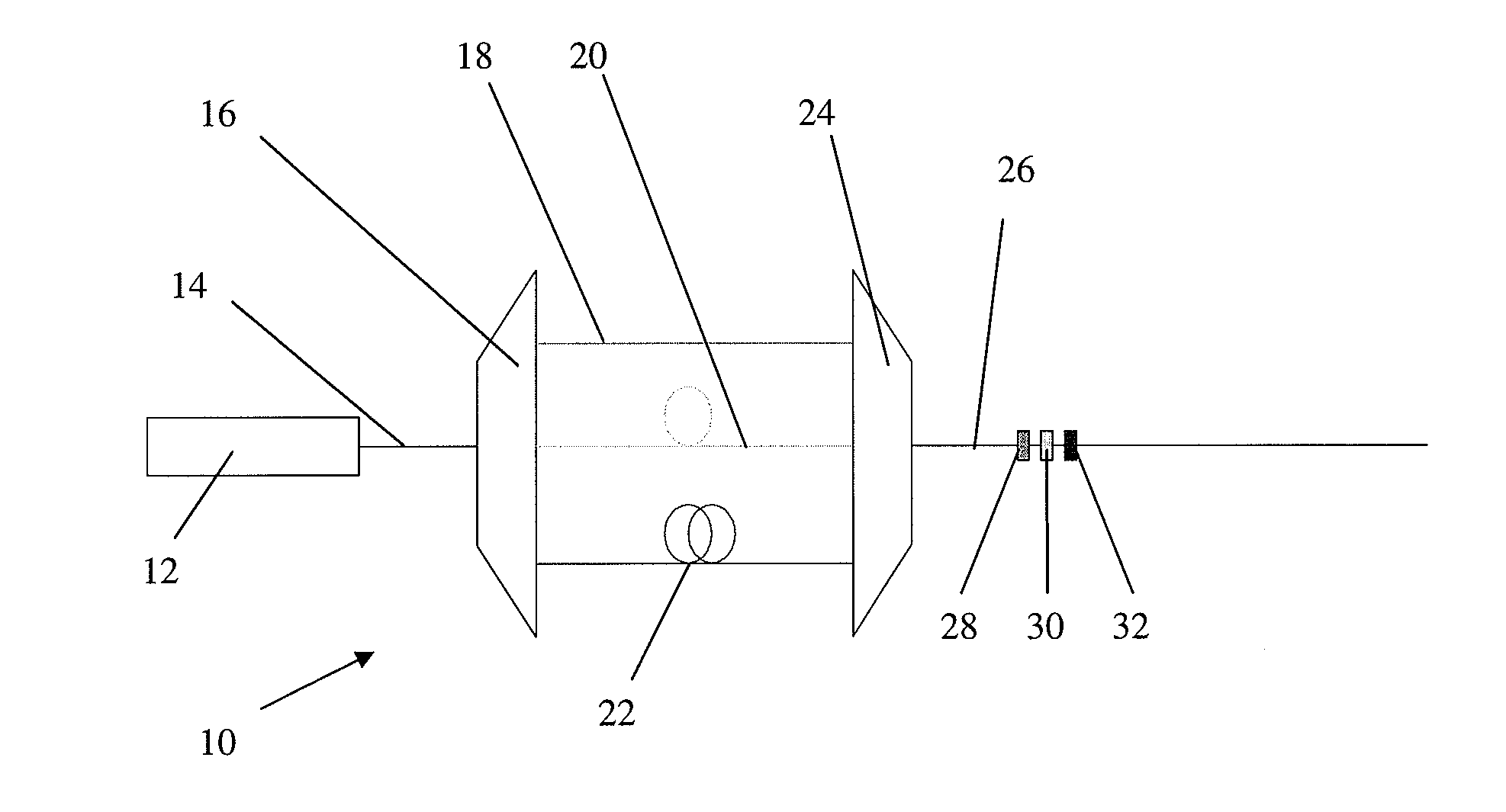
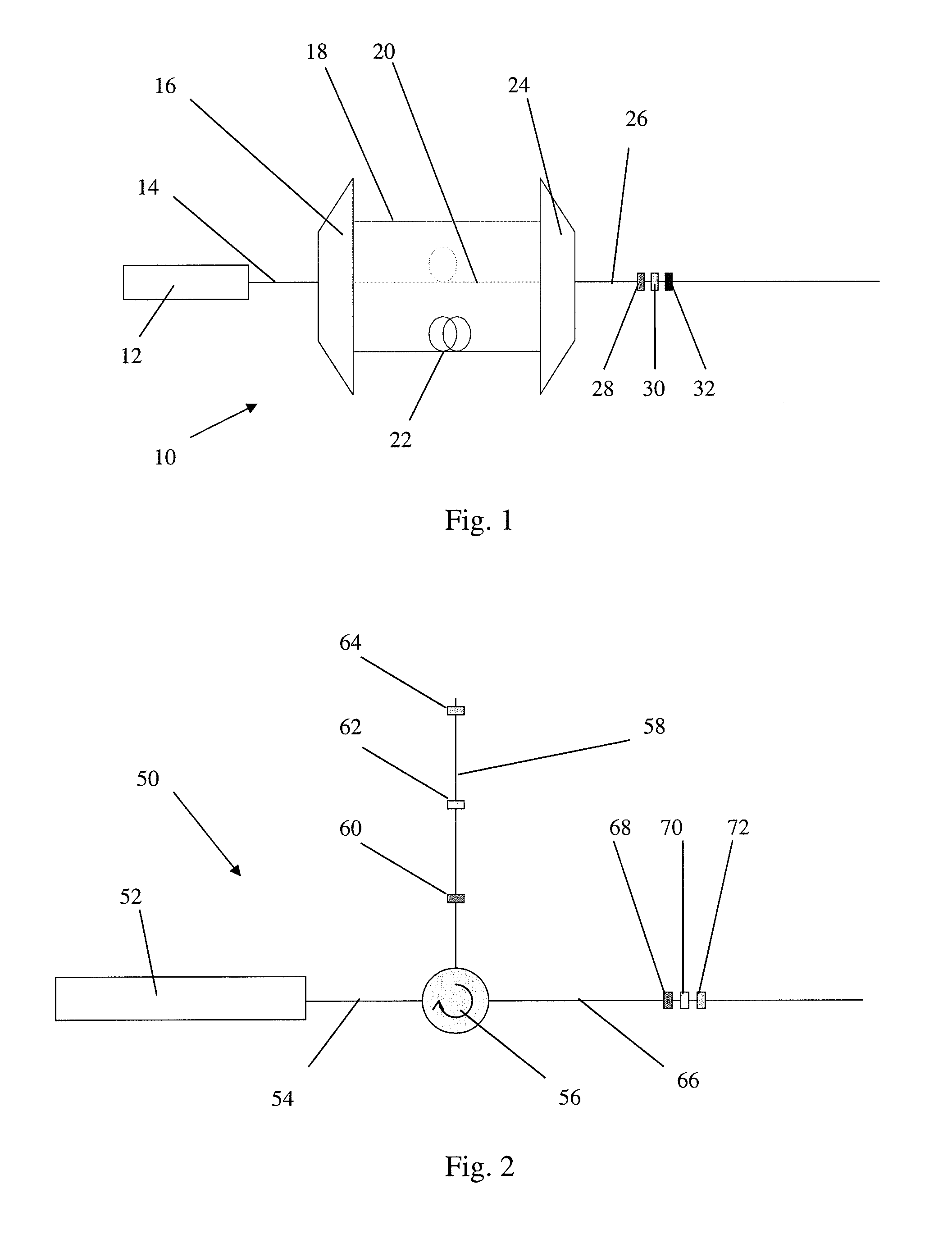
[0018]FIG. 1 shows apparatus for interrogating fibre Bragg gratings (FBGs) comprising a TDM (time-division multiplexing) interrogator 12 connected to a first end of a first optical fibre 14. The other end of the first optical fibre 14 is connected to a wavelength band splitter / combiner 16. The wavelength band splitter / combiner 16 is connected to one end of three delay coils 18, 20 and 22. The other end of the three delay coils 18, 20, 22 is connected to a wavelength band combiner / splitter 24, which in turn is connected to one end of a second optical fibre 26. The second optical fibre 26 comprises fibre Bragg gratings 28, 30, 32 closely spaced along its length. Each of the fibre Bragg gratings 28, 30, 32 has an operating range of resonant wavelengths in a different discrete wavelength band. Each of the wavelength band splitter / combiners 16, 24 is configured to direct light in the wavelength bands corresponding to each of the fibre Bragg gratings 28, 30, 32 into a respective delay coi...


PUM

PropertyMeasurementUnit
distanceaaaaaaaaaa
distanceaaaaaaaaaa
wavelengthsaaaaaaaaaa

Abstract

Apparatus for interrogating an optical fibre comprising a plurality of fibre Bragg gratings each having a resonant wavelength in a different discrete wavelength band. The apparatus comprises a delay arrangement interposed in use in an optical path for light supplied to and/or reflected from the fibre Bragg gratings. The delay arrangement is configured to apply a different time delay to light in each of the discrete wavelength bands, whereby the light reflected from each of the fibre Bragg gratings is received at an interrogator port of the apparatus in a different discrete time interval.

Description

FIELD OF THE INVENTION[0001]This invention relates to apparatus for interrogating fibre Bragg gratings (FBGs).BACKGROUND TO THE INVENTION[0002]Optical fibre strain sensors are known and WO 2004 / 056017 discloses a method of interrogating multiple fibre Bragg grating strain sensors along a single fibre. In the system of WO 2004 / 056017, Bragg gratings are defined in the optical fibre at spaced locations along the optical fibre. When the optical fibre is put under strain, the relative spacing of the planes of each Bragg grating changes and thus the resonant optical wavelength of the grating changes. By determining the resonant wavelength of each grating, a strain measurement can be derived for the location of each grating along the fibre. The light reflected from each fibre Bragg grating is identified by the time of arrival of a reflected light pulse at a detector, such that the reflected signals from multiple gratings in a single fibre are multiplexed in the time domain.[0003]A problem...

Claims


Application Information

Patent Timeline
Patent Type & Authority Applications(United States)
IPC IPC(8): G01N21/17G01N21/00G02B6/00
CPCG01B11/18G01B11/165
Inventor VOLANTHEN, MARKLLOYD, GLYNN
Owner MOOG INSENSYS
Why Eureka
Try Eureka