
Base station interference-free antenna module and WiFi base station mesh network system using the antenna module

a technology of base station and mesh network system, which is applied in the direction of wireless communication, network topologies, wireless commuication services, etc., can solve the problems of poor wireless network transmission efficiency, signal loss, and ineffective improvement of signal to noise ratio (snr) of wireless transmission, so as to increase the wireless transmission efficiency of high frequency signals

Inactive Publication Date: 2010-05-27
INNOVATION WIRELESS
View PDF14 Cites 4 Cited by
  • Summary
  • Abstract
  • Description
  • Claims
  • Application Information

AI Technical Summary

Benefits of technology

[0008]An object of the present invention is to provide a base station interference-free antenna module, which can increase the wireless transmission efficiency of high frequency signals between two WiFi base stations and also the SNR of wireless transmission of high frequency signals.
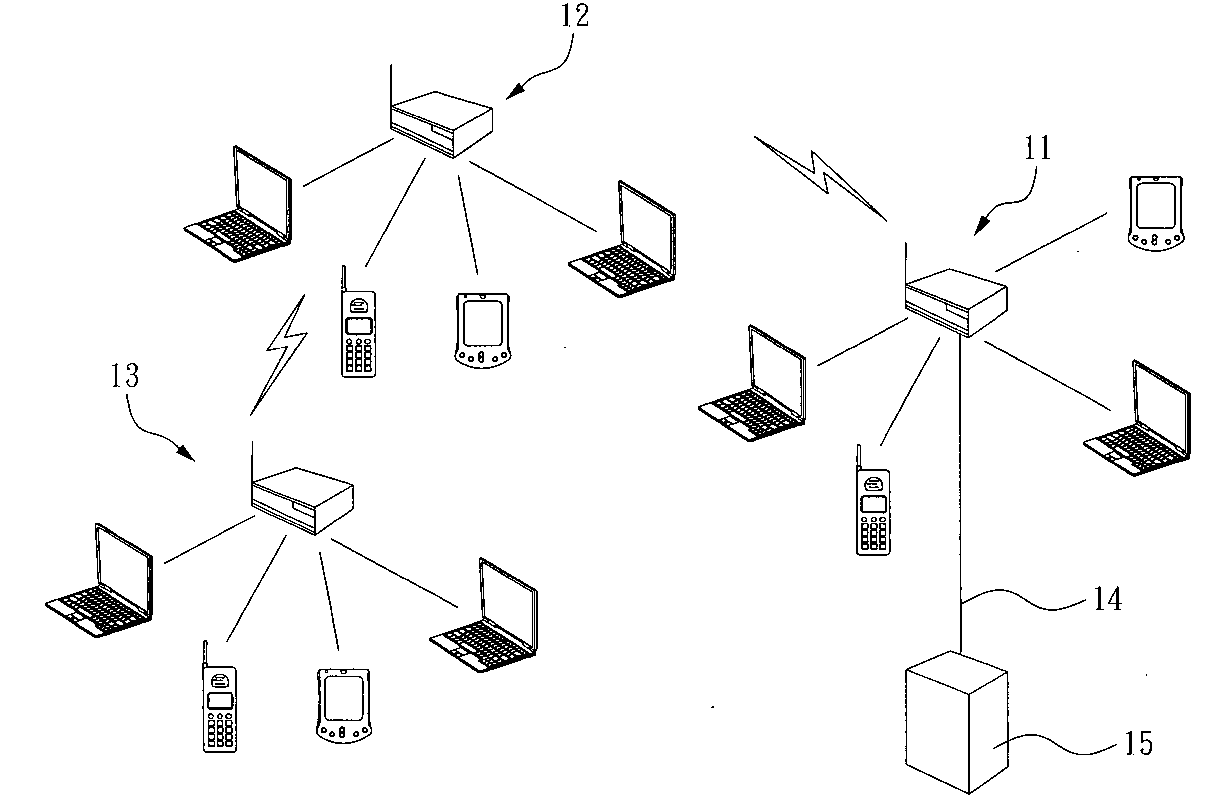
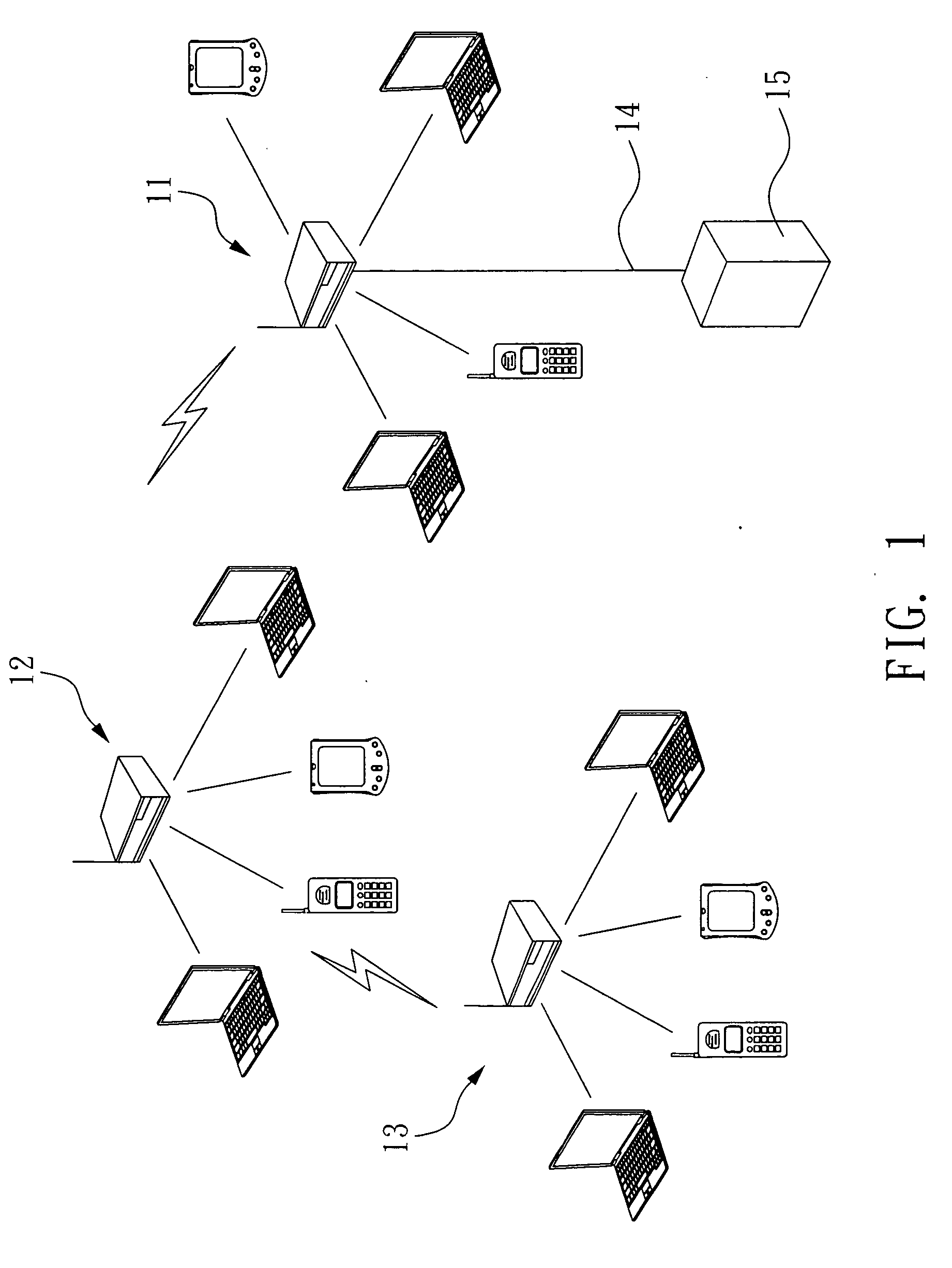
[0009]Another object of the present invention is to provide a WiFi base station mesh network system, which can increase the wireless transmission efficiency of high frequency signals between two WiFi base stations and effectively minimize the deployment density of WiFi base stations while maintaining a desired QoS.
[0012]Therefore, the high frequency signals transmitted by the high frequency transceivers of the base station interference-free antenna module in the invention have a circular polarization characteristic (such as left-hand circular polarization), and when the circularly polarized high frequency signals are reflected by an obstacle (such as a building or vehicle), its circular polarization characteristic would be changed (such as changed from left-hand circular polarization to right-hand circular polarization). Therefore, the antenna controller of the base station interference-free antenna module of a second WiFi base station can deliver only the high frequency signal with a specific circular polarization (such as left-hand circular polarization) to the signal processor by the internal circular polarization filtering property. In this case, even if the reflected high frequency signals are received by the second high frequency transceivers of the second WiFi base station, they cannot enter the signal processor due to the right-hand circular polarization characteristic. Namely, the noises produced by the reflected high frequency signal or signals are effectively suppressed, so the SNR of wirelessly transmitting the high frequency signals can be raised and the wireless transmission efficiency of high frequency signals between two WiFi base stations is raised.
[0013]Similarly, since each high frequency transceiver of the antenna module respectively in the two WiFi base stations of the WiFi base station mesh network system can transmit or receive circularly polarized high frequency signals, the other WiFi base station can easily receive the high frequency signal with the same circular polarization when one WiFi base station transmits the high frequency signal with a specific circular polarization, and the SNR and the transmission efficiency are accordingly raised when wirelessly transmitting the high frequency signals. Therefore, the WiFi base station mesh network system can increase the distance between the WiFi base stations (i.e., reduce the deployment density of the WiFi base stations), while maintaining the desired QoS.

Problems solved by technology

In addition, buildings, moving vehicles and dirty air particles in a metropolitan area can cause poor transmission efficiency of the wireless network.
Thus, the signal to noise ratio (SNR) of wireless transmission could not be improved effectively, and it is likely resulting in signal loss.
However, it causes that the entire deployment cost of the typical WiFi base station mesh network system is largely increased (for it requires more WiFi base stations), and may also affect on the health of people around the WiFi base stations.
However, the smart antenna is very expensive, and the cost could be even higher than the entire WiFi base station.
Thus, for the industry, WiFi base stations with the smart antenna could not be implemented widely.
Therefore, the smart antenna can only solve partial of the aforementioned problems.

Method used


Image

  • Base station interference-free antenna module and WiFi base station mesh network system using the antenna module
  • Base station interference-free antenna module and WiFi base station mesh network system using the antenna module
  • Base station interference-free antenna module and WiFi base station mesh network system using the antenna module

Examples


Embodiment Construction

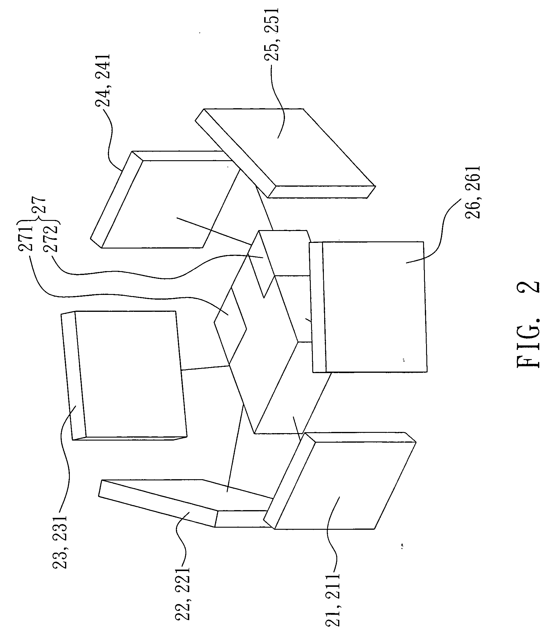
[0020]FIG. 2 is a schematic view of a base station interference-free antenna module according to an embodiment of the invention. As shown in FIG. 2, the module includes a plurality of high frequency transceivers 21 to 26 and an antenna controller 27. The high frequency transceivers 21 to 26 face different directions respectively, and the antenna controller 27 is electrically coupled to the high frequency transceivers 21 to 26 respectively. In addition, the base station interference-free antenna module is implemented in a wireless fidelity (WiFi) base station (shown later) and applied to a high frequency signal transmission between the WiFi base station and another WiFi base station (shown later).

[0021]The WiFi base station (shown later) with the base station interference-free antenna module has a signal processor (shown later), and the antenna controller 27 is electrically coupled to the signal processor (shown later). The antenna controller 27 is based on a signal transmitting / rece...


PUM


Abstract

A base station interference-free antenna module includes a plurality of high frequency transceivers respectively facing different directions, and an antenna controller electrically coupled to the high frequency transceivers. The antenna controller is electrically coupled to a signal processor in order to receive a signal transmitting / receiving request output by the signal processor to accordingly select a high frequency transceiver to transmit or receive a circularly polarized high frequency signal. The system includes two WiFi base stations, each having the base station interference-free antenna module and a signal processor, and the high frequency signals wirelessly transmitted between the WiFi base stations in the system are circularly polarized.

Description

BACKGROUND OF THE INVENTION[0001]1. Field of the Invention[0002]The present invention relates to a base station interference-free antenna module and a wireless fidelity (WiFi) base station mesh network system and, more particularly, to a base station interference-free antenna module capable of improving wireless transmission efficiency of a high frequency signal between two WiFi base stations and the signal to noise ratio (SNR) of wireless transmission of high frequency signals, and the system using the base station interference-free antenna module to effectively reduce the deployment density of WiFi base stations while maintaining the desired quality of service (QoS), in addition to improving the efficiency of wireless transmission of high frequency signals between two WiFi base stations.[0003]2. Description of Related Art[0004]In recent years, WiFi technology has been widely implemented in the wireless network systems of metropolitan areas, and people can access internet wherever ...

Claims


Application Information

Patent Timeline
Patent Type & Authority Applications(United States)
IPC IPC(8): H04W84/02H04W88/08
CPCH01Q1/246H01Q21/205H04W88/08H04W84/18H04W16/28
Inventor CHEN, MICHAELCHOU, MING-CHEN
Owner INNOVATION WIRELESS
Learn More