Roughing cut edge insert with a finishing wiper

a technology of cutting edge inserts and wipers, which is applied in the direction of cutting inserts, shaping cutters, manufacturing tools, etc., can solve the problems of limiting the possible feed rate below the suitable rate, time-consuming and expensive operations, etc., and achieves good results and higher feed rates.

Inactive Publication Date: 2010-05-27
KENNAMETAL INC
View PDF35 Cites 29 Cited by
  • Summary
  • Abstract
  • Description
  • Claims
  • Application Information

AI Technical Summary

Benefits of technology

[0006]Accordingly, there is a general need in the art for a single cutting insert that includes both a primary roughing cutting edge and a secondary finishing cutting edge to sequentially perform with a single insert roughing cutting and finishing cutting operations and that permits this sequential cutting operation to be conducted on a lathe or other machine at a higher feed rate suitable for roughing cutting operations while still achieving good results for both operations.

Problems solved by technology

Such operations are time consuming and expensive since multiple cutting inserts must be used to machine a single workpiece to a desired shape and operations must be periodically halted in order to replace the inserts for different cutting operations.
Thus, inserts such as the one disclosed by Eklund et al. limit the possible feed rate below what is suitable for normal rough cutting operations.

Method used


Image

  • Roughing cut edge insert with a finishing wiper
  • Roughing cut edge insert with a finishing wiper
  • Roughing cut edge insert with a finishing wiper

Examples


Embodiment Construction

[0019]For purposes of the description hereinafter, spatial orientation terms, if used, shall relate to the referenced embodiment as it is oriented in the accompanying drawing figures or otherwise described in the following detailed description. However, it is to be understood that the embodiments described hereinafter may assume many alternative variations and embodiments. It is also to be understood that the specific devices illustrated in the accompanying drawing figures and described herein are simply exemplary and should not be considered as limiting.

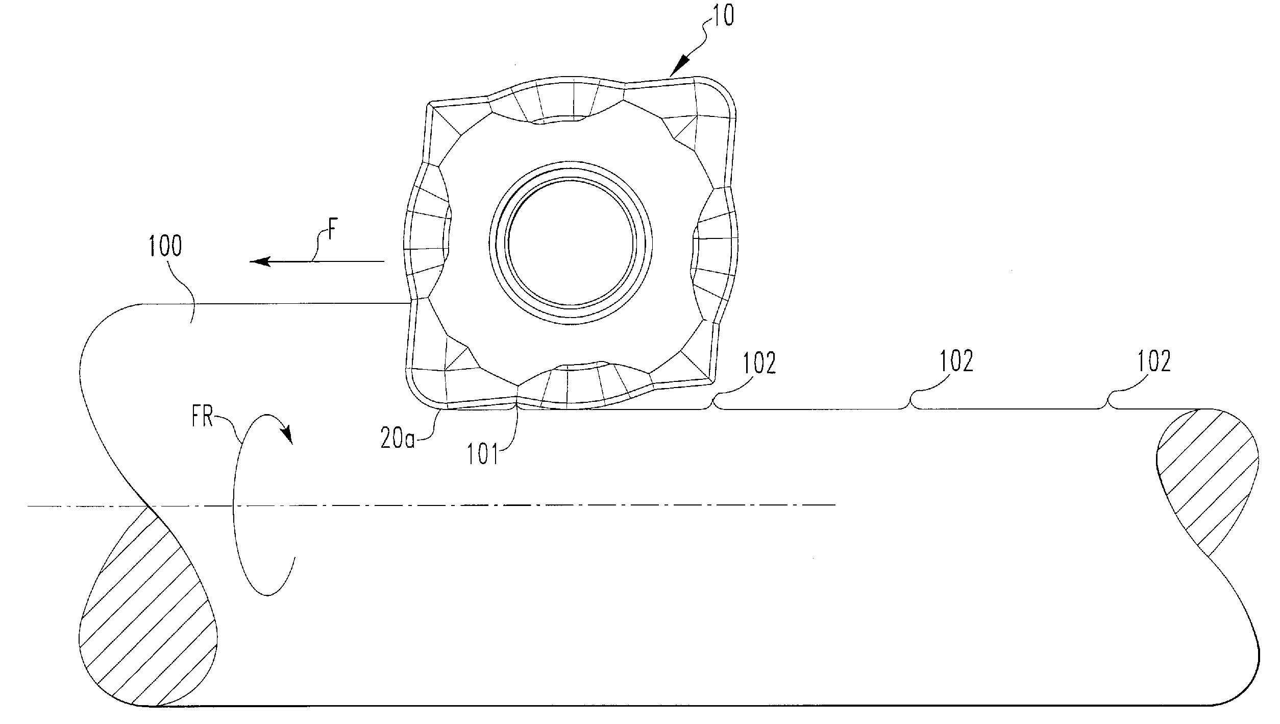
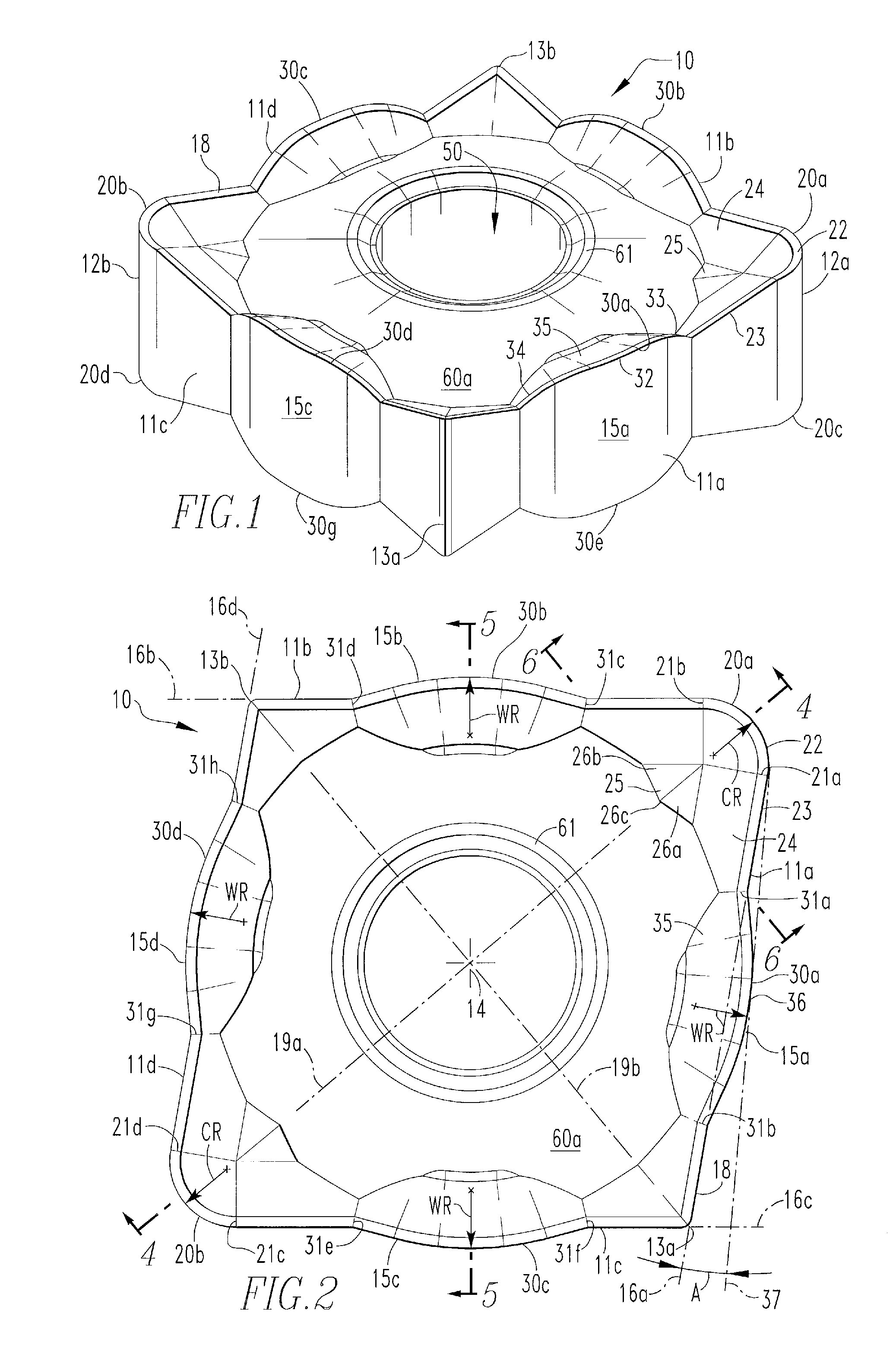
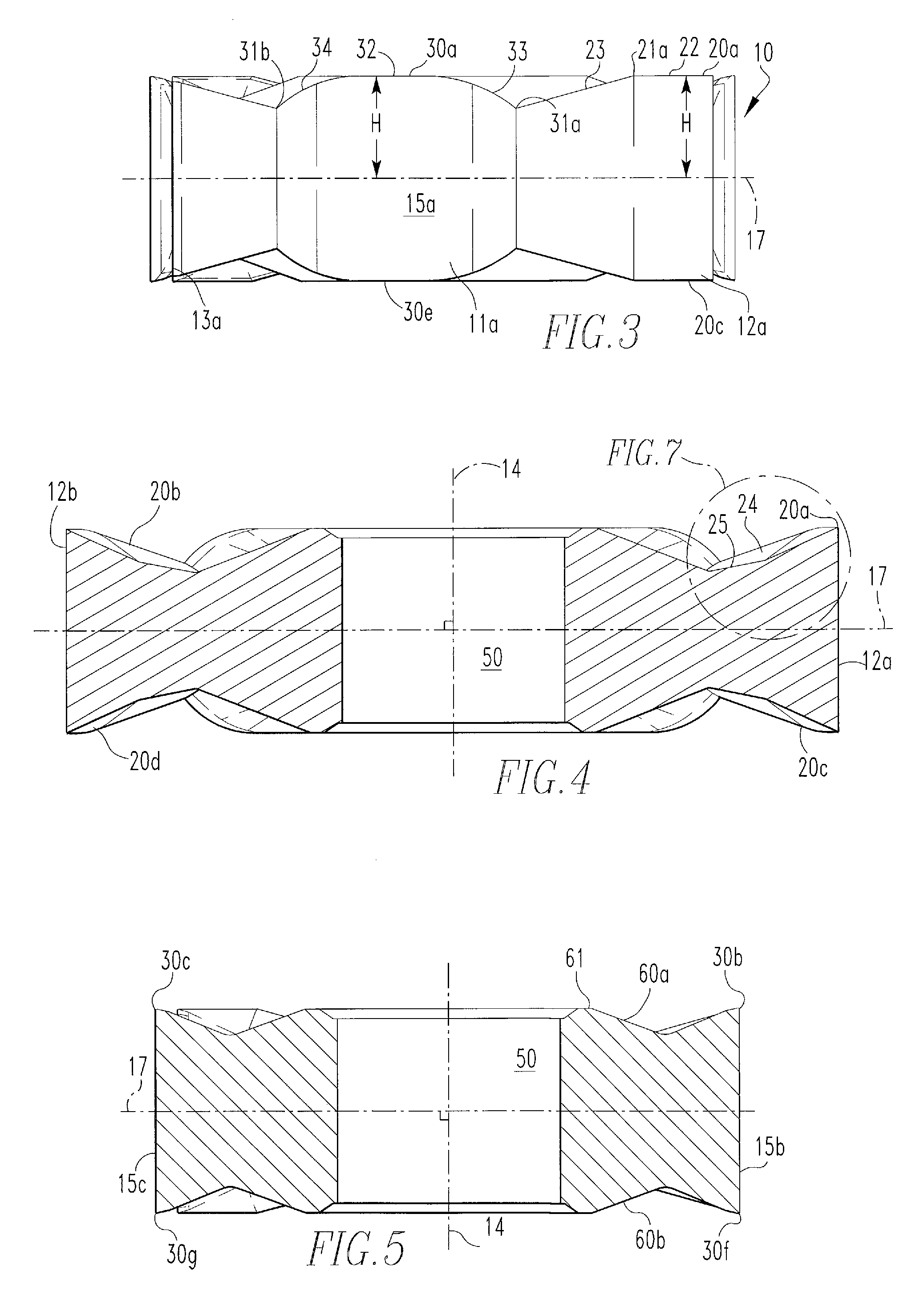
[0020]Referring to FIGS. 1-7, an indexable cutting insert according to an embodiment of the present invention is shown. A plurality of lines are provided in the drawings across the surfaces and features of the insert in order to connote the continuous curvature of the surfaces, which as a result, will not have distinct lines to highlight discontinuities. It is to be appreciated, though, that any curved surfaces shown and described h...


PUM

PropertyMeasurementUnit
angleaaaaaaaaaa
cutting angleaaaaaaaaaa
corner radiusaaaaaaaaaa

Abstract

An indexable cutting insert having a body with a central axis extending therethrough and including two opposing surfaces interconnected by at least three sides. First and second sides intersect with one of the opposing surfaces at a primary corner to form a primary cutting edge having a corner radius. First and third sides intersect at a secondary corner. An intersection between an intermediate portion of the first side and the opposing surface forms a secondary cutting edge having an arcuate shape with a radius extending away from the central axis beyond a line between the primary corner and the secondary corner. An end of the secondary cutting edge is spaced from the end of the corner radius on the first side at a distance at least approximately one-eighth of a length of the line between the end of the corner radius on the first side and the secondary corner.

Description

BACKGROUND OF THE INVENTION[0001]1. Field of the Invention[0002]The present invention relates to an indexable cutting insert having a roughing cut edge combined with a finishing wiper edge. More particularly, the present invention relates to an indexable cutting insert having a roughing cut edge with a corner radius and a finishing cutting edge spaced from the roughing cut edge.[0003]2. Description of Related Art[0004]Typical metalworking turning operations are conducted with a lathe or similar tool using a cutting insert. First, machining is undertaken with one or more inserts suitable for rough cutting, which removes large amounts of material from a workpiece but leaves a relatively rough surface finish. Then, the roughly turned surface is machined by another insert configured to give the workpiece a finished cut. Such operations are time consuming and expensive since multiple cutting inserts must be used to machine a single workpiece to a desired shape and operations must be peri...

Claims


Application Information

Patent Timeline
Patent Type & Authority Applications(United States)
IPC IPC(8): B26D3/00
CPCB23B27/141B23B2200/081B23B2200/123B23B2200/125Y10T407/235B23B2200/204B23B2200/208B23B2220/445B23B2270/14B23B2200/202
Inventor MORRISON, LEWIS RAY
Owner KENNAMETAL INC
Why Eureka
Try Eureka