Attachment Devices on a Wind Turbine Blade and a Method of Servicing Utilising these Device

Active Publication Date: 2010-05-27
LM GLASSFIBER
View PDF1 Cites 19 Cited by
  • Summary
  • Abstract
  • Description
  • Claims
  • Application Information

AI Technical Summary

Benefits of technology

[0018]One embodiment of the method according to the invention further relates to positioning of the blade in an essentially horizontal position and/or turning the blade about its longitudinal axis. Hereby all areas of the blade can be made accessible with a view to repair or other kind of servicing, and moreover the blade can be positioned optimally relative to attachment of eg a working platform or a covering tent. Turning of the blade about its longitudinal axis or pitching of the blade may also cause the front and rear edges of the blade to face upwards or downwards as needed in connection with the servici

Problems solved by technology

Inspection and repair of blades on wind turbines are associated with high financial costs, on the one hand in the form of loss of earnings while the turbine is out of operation and, on the other, by the work itself.
However, the costs involved in such course of action are considerable, on the one hand for the new blade, on the other for crane, ship or helicopter for the mounting, to which is to be added that the replacement is possible only in calm weather conditions, which may pose a problem in particular in case of off-shore turbines.
Alternatively, inspection can be performed by the crew rappelling down the blade from the nacelle which, however, is difficult to accomplish in adequately safe conditions.
The use of both mobile cranes and ships with cranes is, however, as mentioned above, associated with high costs.
Add to this tha

Method used


Image

  • Attachment Devices on a Wind Turbine Blade and a Method of Servicing Utilising these Device
  • Attachment Devices on a Wind Turbine Blade and a Method of Servicing Utilising these Device
  • Attachment Devices on a Wind Turbine Blade and a Method of Servicing Utilising these Device

Examples


Embodiment Construction

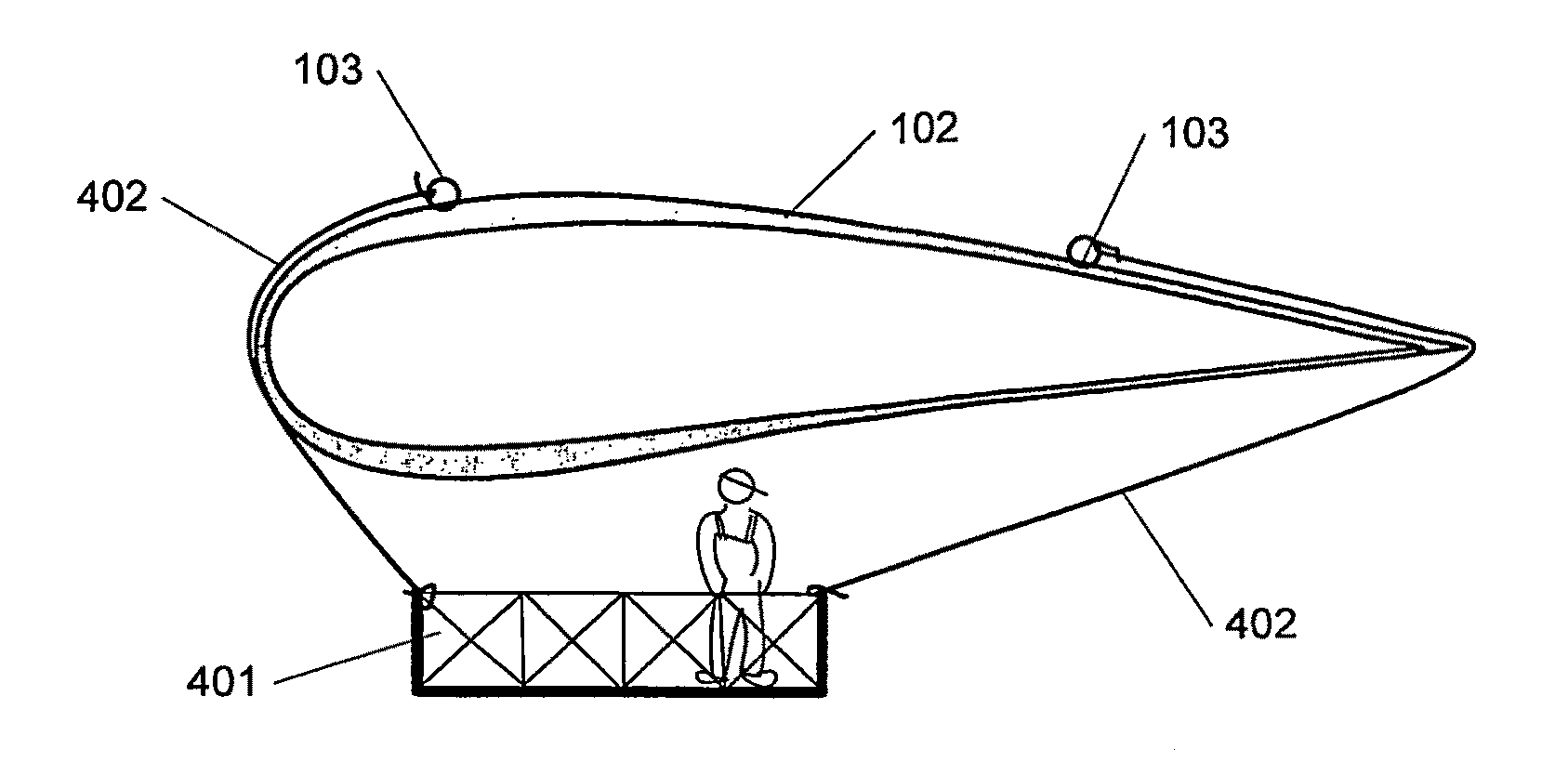
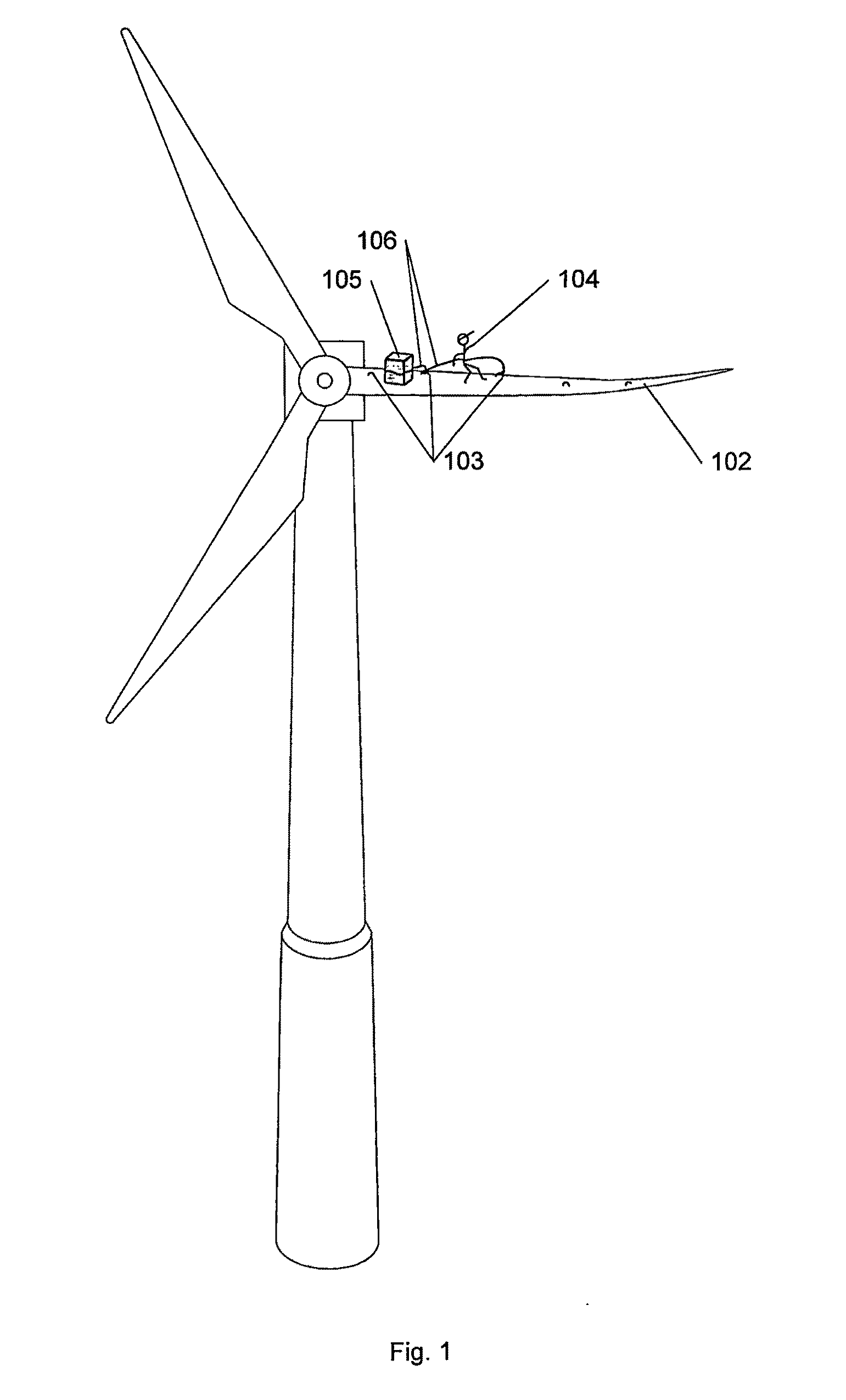
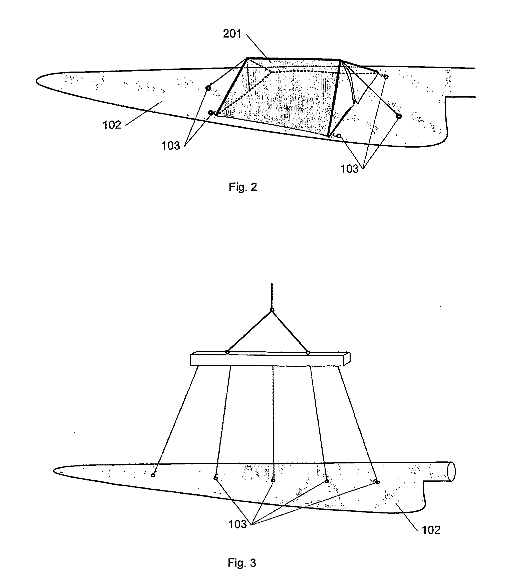
[0031]FIG. 1 shows a wind turbine 101, seen from the front, wherein the one of the pre-curved blades 102 is positioned in its horizontal or approximately horizontal position in order to enable repair or servicing in accordance with the invention. Usually a blade is repaired or inspected while in its vertical position while the crew 104 are in suspended working platforms or are suspended from the nacelle and rappel down the blade. As shown in FIG. 1 the blade according to the invention is equipped with a number of attachment devices 103 to which crew 104 and / or servicing equipment 105 can be attached. Hereby it is accomplished that the crew 104 is able to move about safely on the blade 102 as such while it is in its horizontal position. This also enables that it is possible to repair more comprehensive and more complex damage to the blade than would otherwise have been possible on vertical faces, and it follows that it is more frequently possible to avoid the costs involved in dismou...


PUM

PropertyMeasurementUnit
Aerodynamicaaaaaaaaaa

Abstract

the present invention relates to a table for a wind turbine equipped with attachment devices 103 for attaching servicing equipment, 401, 402, said attachment means being attached at and accessible from the blade exterior. They may be located in cavities and be covered when not in use. Hereby it is accomplished that the blade can be serviced and repaired while positioned horizontally without the attachment devices as such otherwise influencing the aerodynamic properties of the blade. One possibility is that during manufacturing such a cavity is closed but the cavity can later be broken open. Additionally, the invention relates to a wind turbine featuring such blade and a method of servicing a blade when mounted on a wind turbine, wherein servicing equipment is attached to at least one attachment device in the blade. It is furthermore mentioned, that the attachment devices might be used when mounting a blade.

Description

[0001]The invention relates to a blade for a wind turbine and a method of servicing such blade mounted on a wind turbine.BACKGROUND[0002]Inspection and repair of blades on wind turbines are associated with high financial costs, on the one hand in the form of loss of earnings while the turbine is out of operation and, on the other, by the work itself. It is an option to dismount the damaged blade and mount another one straightaway, whereby the operation of the turbine can swiftly be resumed. However, the costs involved in such course of action are considerable, on the one hand for the new blade, on the other for crane, ship or helicopter for the mounting, to which is to be added that the replacement is possible only in calm weather conditions, which may pose a problem in particular in case of off-shore turbines.[0003]Servicing and repair of the blade may in most instances, unless the damage is to extensive, also be performed while the blade is mounted on the wind turbine. This is usu...

Claims


Application Information

Patent Timeline
IPC IPC(8): F03D11/00B23P6/00
CPCF03D1/003F03D1/0658F03D11/00F03D11/0033Y10T29/49318F05B2230/80F05B2260/30Y02E10/721Y02E10/722F05B2220/25F03D80/00F03D80/30F03D80/50Y02E10/72Y02P70/50
Inventor GRABAU, PETER
Owner LM GLASSFIBER
Why Eureka
Try Eureka