Spline shaft

a shaft and shaft technology, applied in the field of shafts, can solve the problems of body vibration and noise, increased static friction coefficient, and possible stick slippage, and achieve the effects of preventing the degradation of substrate strength more securely

Inactive Publication Date: 2010-05-27
JTEKT CORP
View PDF10 Cites 15 Cited by
  • Summary
  • Abstract
  • Description
  • Claims
  • Application Information

AI Technical Summary

Benefits of technology

[0005]The present invention is one which has been done in view of such circumstances, and its object is to provide a spline shaft, which can securely suppress the occurrence of stick slip by means of measures other than just simply making the surface roughness smaller.
[0027]Moreover, it is allowable to interpose a lubricant between the outer-peripheral spline and the inner-peripheral spline. By means of this, it is possible to make the longevity of the outer-peripheral spline and inner-peripheral spline longer while making the static friction coefficient between them smaller adequately.

Problems solved by technology

And, because of the stick slip, body vibrations and noises come to occur.
However, in the case of setting the surface roughness at such a very low value as low as Rz (10-point average roughness based on JIS B 0601: 1994, and being the same hereinafter) 0.1 μm or less, for instance, the static friction coefficient has increased adversely because of the squeeze effect, and the like.
And, by means of the fact that the dynamic friction coefficient with respect to the sliding speed thus becomes a negative gradient, there is a fear that the stick slip might occur.

Method used


Image

  • Spline shaft
  • Spline shaft
  • Spline shaft

Examples


Embodiment Construction

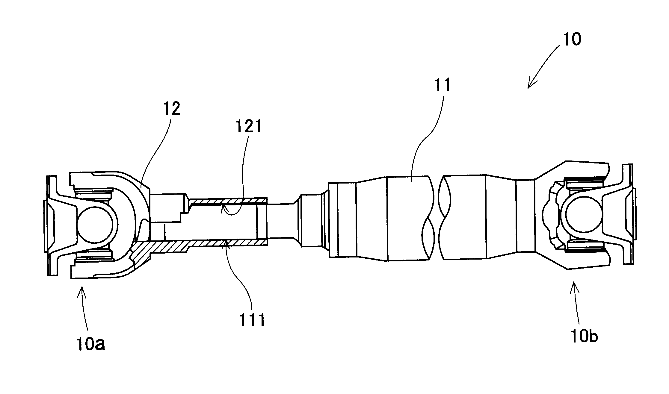
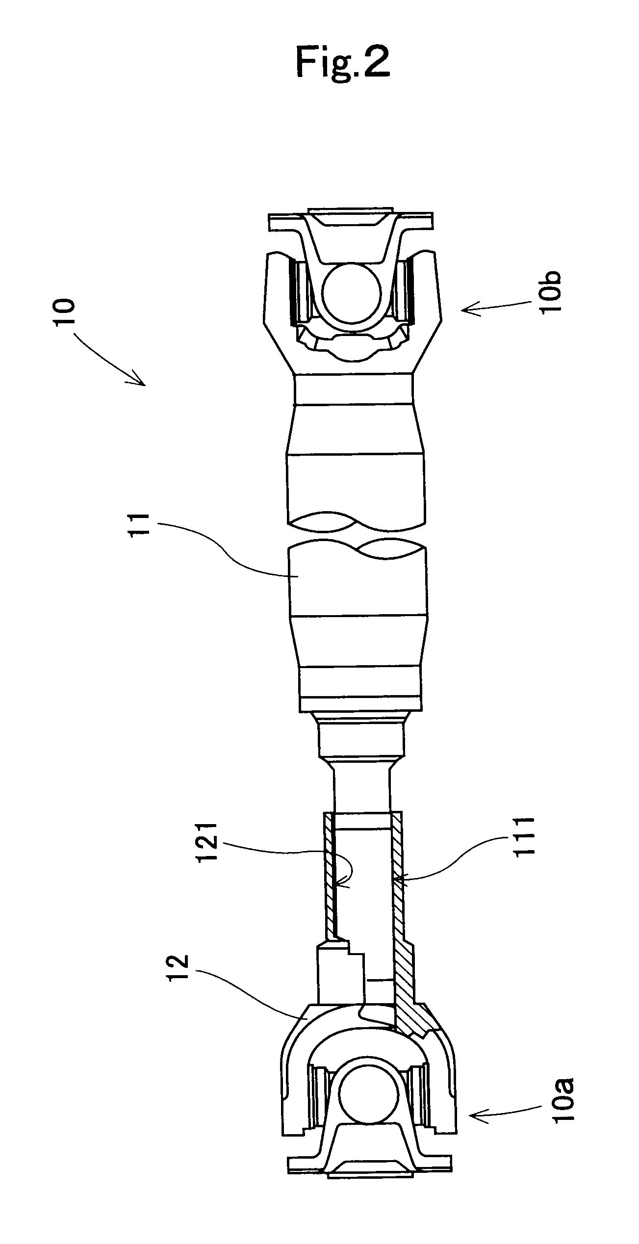
[0037]Next, specific examples will be named hereinafter to explain the present invention in more detail. A case where a spline shaft according to the present invention is applied to the propeller shaft 10, which is boarded on vehicle, will be named hereinafter as an example to explain it.

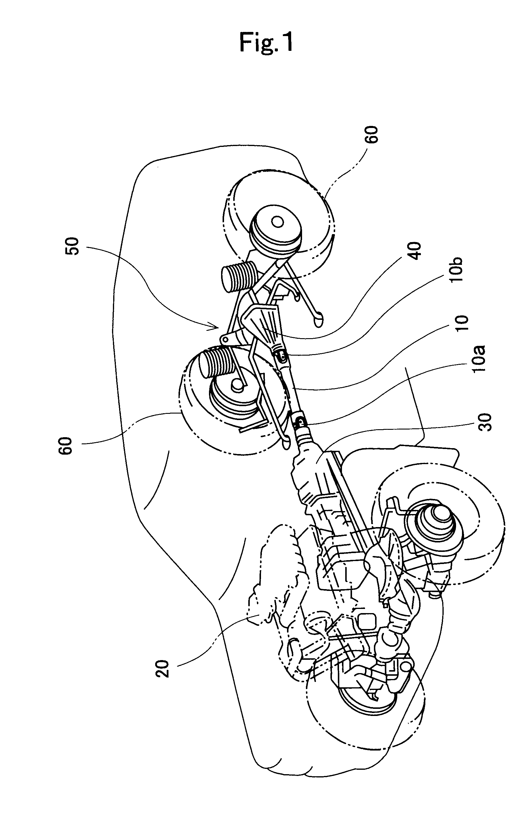
[0038](1) Construction of Driving System for Vehicle

[0039]First of all, a construction of a driving system for vehicle, to which the propeller shaft 10 is applied, will be explained with reference to FIG. 1. Here, FIG. 1 is a perspective diagram for illustrating a construction of a driving system for vehicle. As shown in FIG. 1, the vehicle is a front engine rear drive (FR) car. Specifically, a driving system of the vehicle is equipped with an engine 20 (the power unit in the present invention), which is disposed in vehicular front, a transmission 30, a propeller shaft 10, a differential gear 40, and a rear axle 50.

[0040]The transmission 30 is disposed on the front side of the vehicle, and is placed...


PUM


Abstract

A spline shaft that can suppress occurrence of stick slip by measures other than just simply making the surface roughness smaller. The spline shaft includes a first shaft with an outer-peripheral spline formed, and a second shaft with an inner-peripheral spline, which engages with the outer-peripheral spline peripherally and that is made slidable axially, formed. And, at least either one of the outer-peripheral spline and the inner-peripheral spline includes a substrate whose surface is formed to a predetermined surface roughness, and an amorphous carbon-system hard thin film, which coats and forms the surface of substrate.

Description

TECHNICAL FIELD[0001]The present invention is one that relates to a spline shaft for transmitting torque while making it possible to move relatively to each other in axial-line direction.BACKGROUND ART[0002]As an example of spline shafts, there is a propeller shaft that transmits the driving force of powder unit, which is boarded on vehicle, to wheel. This propeller shaft is placed between transmission, which is connected to power unit, and differential gear, which is connected to wheel, thereby transmitting the output of the transmission to the differential gear. Here, depending on shocks from road surface and vehicle's driving conditions, and the like, the relative positional relationship between the transmission and the differential gear moves. In particular, in order to absorb the relative position's movement in the front / rear direction of vehicle, the propeller shaft is divided into a first shaft, which is provided with an outer-peripheral spline, and a second shaft, which is p...

Claims


Application Information

Patent Timeline
Patent Type & Authority Applications(United States)
IPC IPC(8): F16D3/06F16C3/02B05D3/00
CPCB60K17/22B60K17/24F16D2300/10F16D3/06F16D2001/103F16D1/101
Inventor ANDO, JUNJISENGA, YOSHIAKISUZUKI, TOMOOAOKI, KAZUNORISAITO, TOSHIYUKIKUWABARA, HIROFUMI
Owner JTEKT CORP
Why Eureka
Try Eureka