
Method for determining flow and flow volume through a vessel

a flow and volume measurement and flow volume technology, applied in the field of ultrasound imaging systems and methods, can solve the problems of large error in the calculation of cross-sectional area, incongruity of cvi-q and sdi techniques, and large error in sdi mainly caused by inaccurate diameter measurements, so as to accurately measure flow and flow volume

Inactive Publication Date: 2010-05-27
MAIN JOAN CAROL +4
View PDF4 Cites 31 Cited by
  • Summary
  • Abstract
  • Description
  • Claims
  • Application Information

AI Technical Summary

Benefits of technology

[0012]The present invention overcomes the aforementioned drawbacks by providing a method to non-invasively and more accurately measure flow and flow volume in the vessels of patients. The method includes comprises the steps of acquiring ultrasound data from the subject and producing a 2D Doppler image, generating a 3D representation of the 2D Doppler image in which blood vessel walls are identified by changes in at least one of color, hue, brightness, and intensity, windowing the acquired ultrasound data based on the 3D representation, and automatically identifying a selected depth range in the windowed ultrasound data stretching from a first identified

Problems solved by technology

Both the CVI-Q and SDI techniques are inconsistent in estimations of blood flow volume, although the inconsistency is less for CVI-Q than for SDI.
The error of SDI mainly comes from inaccurate diameter measurements on a static gray scale image, with the assumption of a stable vessel.
Small errors in the diameter measurement result in large errors in the calculation of cross-sectional area and, thus, flow volume.
Although CVI-Q provides more accurate diameter measurements than SDI, both techniques are subject to other significant sources of error, including angle correction error, turbulent flow error, off axis sampling error, and error caused by the pulsing of the vessel being measured.

Method used


Image

  • Method for determining flow and flow volume through a vessel
  • Method for determining flow and flow volume through a vessel
  • Method for determining flow and flow volume through a vessel

Examples


Embodiment Construction

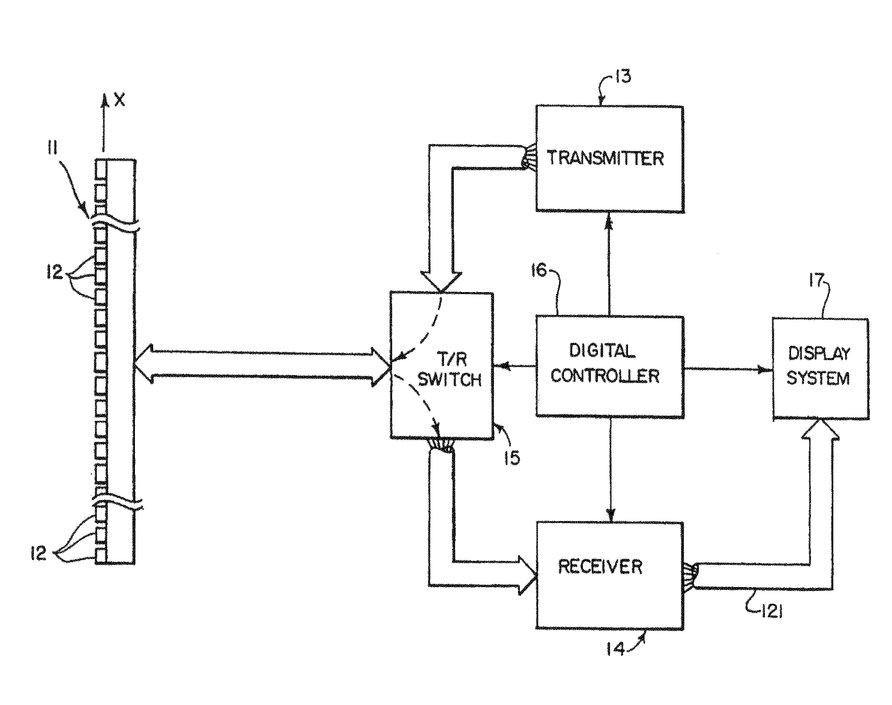
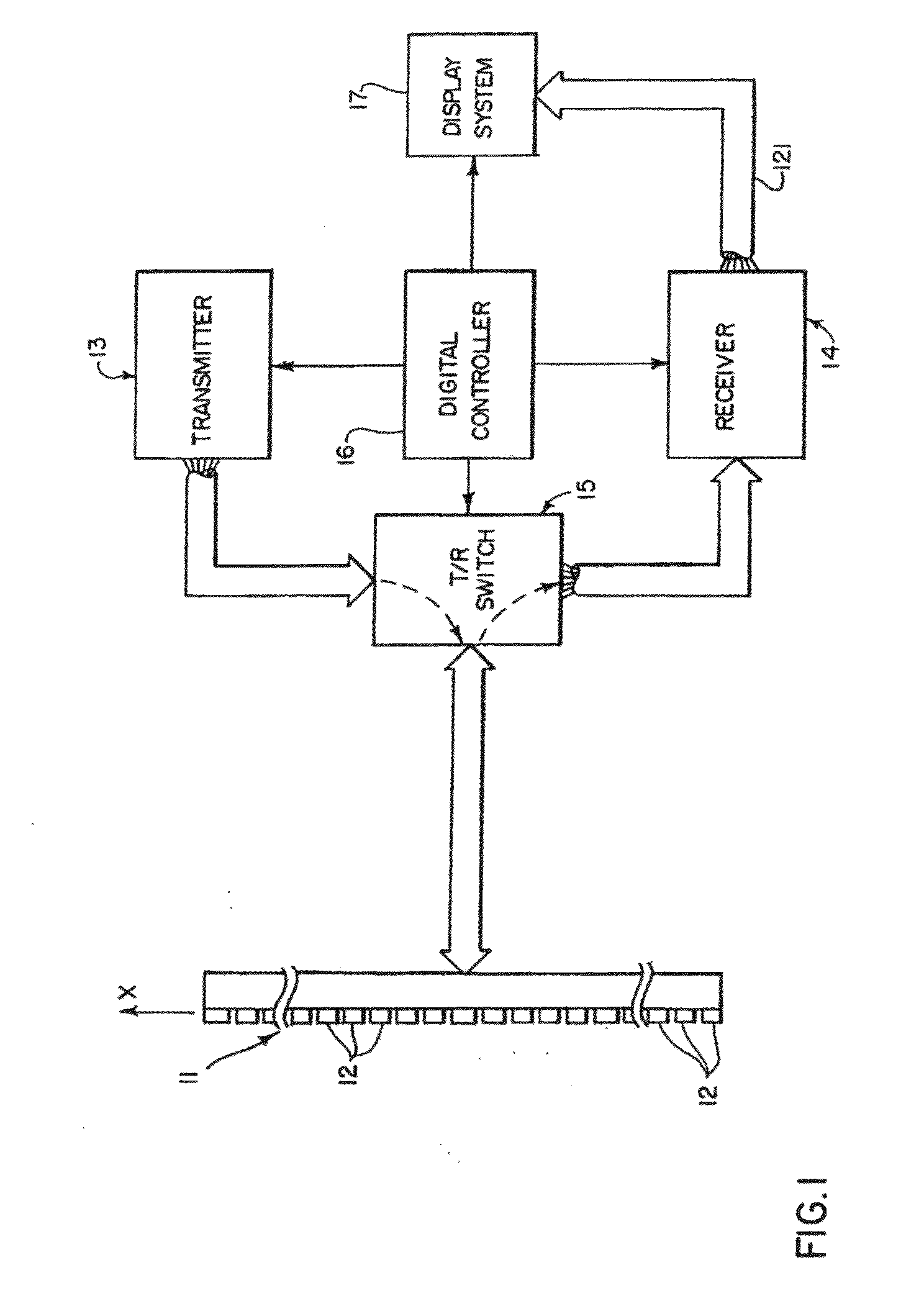
[0025]Referring particularly to FIG. 1, an ultrasonic imaging system includes a transducer array 11 comprised of a plurality of separately driven elements 12 that each produce a burst of ultrasonic energy when energized by a pulse produced by a transmitter 13. The ultrasonic energy reflected back to the transducer array 11 from the subject under study is converted to an electrical signal by each transducer element 12 and applied separately to a receiver 14 through a set of switches 15. The transmitter 13, receiver 14 and the switches 15 are operated under the control of a digital controller 16 responsive to the commands input by the human operator. A complete scan is performed by acquiring a series of echoes in which the switches 15 are set to their transmit position, the transmitter 13 is gated on momentarily to energize each transducer element 12, the switches 15 are then set to their receive position, and the subsequent echo signals produced by each transducer element 12 are appl...


PUM


Abstract

A method for measuring and displaying flow and flow volume in the vessel of a subject. The method includes acquiring ultrasound data from a subject and producing a color Doppler m-mode image depicting the vessel. A 3D representation of the color Doppler m-mode image is then generated to enable an operator to identify the blood vessel and window the ultrasound data accordingly to a selected range of heart beats. Blood vessel walls are automatically identified from the windowed ultrasound data and blood flow through the vessel lumen is measured using pulsed Doppler ultrasound, which is gated to substantially exclude data from outside the lumen. Volume flow through the vessel is determined by multiplying the measured blood flow with a calculated cross-sectional area of the vessel and an image indicative of the volume is then generated and displayed.

Description

CROSS REFERENCE TO RELATED APPLICATIONS[0001]This application is based on, claims the benefit of, and incorporates herein by reference U.S. Provisional Application Ser. No. 61 / 135,043, filed Jul. 16, 2008, and entitled “Method for Displaying Flow and Flow Volume Through a Vessel.”BACKGROUND OF THE INVENTION[0002]The present invention relates to systems and methods for ultrasound imaging and, more particularly, to a system and method for using ultrasound data to measure and display flow and flow volume through a vessel with increased accuracy.[0003]There are a number of modes in which ultrasound can be used to produce images of objects. The ultrasound transmitter may be placed on one side of the object and the sound transmitted through the object to the ultrasound receiver placed on the other side (“transmission mode”). With transmission mode methods, an image may be produced in which the brightness of each pixel is a function of the amplitude of the ultrasound that reaches the recei...

Claims


Application Information

Patent Timeline
IPC IPC(8): A61B8/06
CPCA61B5/02007A61B5/489A61B8/06A61B8/13A61B8/543G01S15/8993G01F1/72G01S7/52066G01S7/52071G01S15/8979G01F1/663
Inventor MAIN, JOAN CAROLTAJIK, JAMILKHANDHERIA, BIJOYLUSK, JOAN L.UMLAND, MATT
Owner MAIN JOAN CAROL
Learn More