Vehicle control apparatus

a technology for controlling apparatus and vehicles, applied in electric control, speed sensing governors, instruments, etc., can solve the problems of poor fuel consumption and inability to maintain the fuel cut state for a long time, and achieve the effect of improving fuel consumption and fuel consumption

Inactive Publication Date: 2010-05-27
TOYOTA JIDOSHA KK
View PDF7 Cites 36 Cited by
  • Summary
  • Abstract
  • Description
  • Claims
  • Application Information

AI Technical Summary

Benefits of technology

[0019]The problem-solving principles of the invention will be described. First, even if engine revolutions temporarily drop due to variations in the operating state of the vehicle, the variations in the hardware of the vehicle, or the like mentioned above when downshift control is performed during execution of fuel cut control, the engine revolutions always increase when a downshift starts (when an inertia phase starts), and the possibility of engine stalling is reduced. Accordingly, even when the fuel cut reset revolutions are set to a lower side than those for normal control, stall resistance can be secured.
[0020]Focusing on such points, in the present invention, for downshift control during execution of fuel cut control, the fuel cut reset revolutions are set lower than the fuel cut reset revolutions for normal control. Such a setting enables fuel cut to be maintained, so an improvement in fuel consumption can be achieved. Moreover, because it becomes unnecessary to set gearshift lines (downshift gearshift lines) to a higher vehicle speed side, it becomes possible to maintain fuel cut while suppressing the occurrence of a gearshift shock.
[0023]In a first specific configuration, when engine revolutions have decreased to the fuel cut reset revolutions when executing the downshift control during the fuel cut control, a gearshift point (downshift gearshift line) for next downshift control during fuel cut control is changed to a higher vehicle speed side. According to this configuration, even when engine revolutions have reached the fuel cut reset revolutions and fuel cut is canceled (fuel injection is resumed), fuel cut control can be maintained in the next downshift control during execution of fuel cut control, so an improvement in fuel consumption can be achieved.
[0024]In another specific configuration, when engine revolutions have a margin with respect to the fuel cut reset revolutions when executing the downshift control during the fuel cut control, a gearshift point for next downshift control during fuel cut control is changed to a lower vehicle speed side. In this case, a downshift gearshift point (downshift gearshift line) for the next downshift control during execution of fuel cut control is set to a lower vehicle speed side by calculating the difference (margin: see FIG. 12A) between the current engine revolutions and the fuel cut reset revolutions and taking that margin into consideration, whereby the occurrence of a gearshift shock can be suppressed more effectively.
[0025]In another specific configuration, when engine revolutions have decreased to the fuel cut reset revolutions while executing the downshift control during the fuel cut control, a control timing of a release-side oil pressure of a hydraulic type frictionally engaging apparatus of the automatic transmission is delayed when next downshift control during fuel cut control is performed. With such delay control, the amount of undershoot (see FIG. 13) of the engine revolutions during downshift control can be reduced, making it possible to control the engine revolutions so as not to reach the fuel cut reset revolutions. As a result, fuel cut control and deceleration lockup slippage control can be maintained in the next downshift control during execution of fuel cut control, so an improvement in fuel consumption can be achieved.

Problems solved by technology

In such a condition, even if the engine revolutions exceed the fuel cut start revolutions after a downshift and the fuel cut control is resumed, the fuel cut state cannot be maintained for a long period of time.
This may cause poor fuel consumption.

Method used


Image

  • Vehicle control apparatus
  • Vehicle control apparatus
  • Vehicle control apparatus

Examples


Embodiment Construction

[0054]Hereinafter, embodiments of the present invention will be described with reference to the drawings.

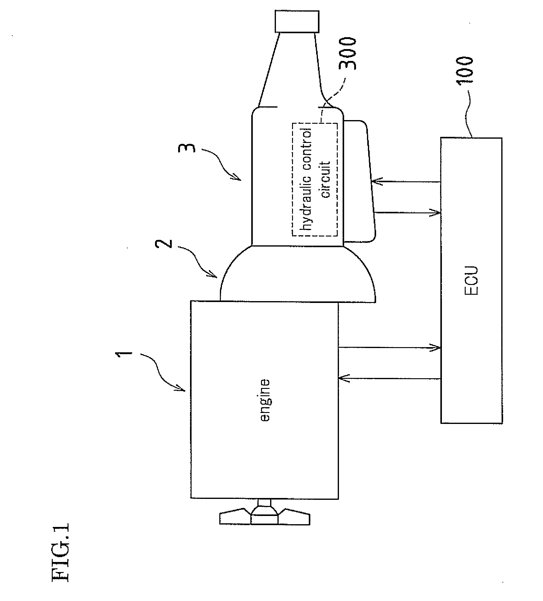
[0055]FIG. 1 is a schematic configuration view that shows a vehicle in which the present invention is applied.

[0056]The vehicle in this example has an FR (front engine / rear drive) configuration, and is provided with an engine 1, an automatic transmission 3 having a torque converter 2, an ECU 100, and so forth, and a vehicle control apparatus of the present invention is realized by a program executed by the ECU 100. Each of the engine 1, the torque converter 2, the automatic transmission 3, and the ECU 100 is described below.

[0057]—Engine—

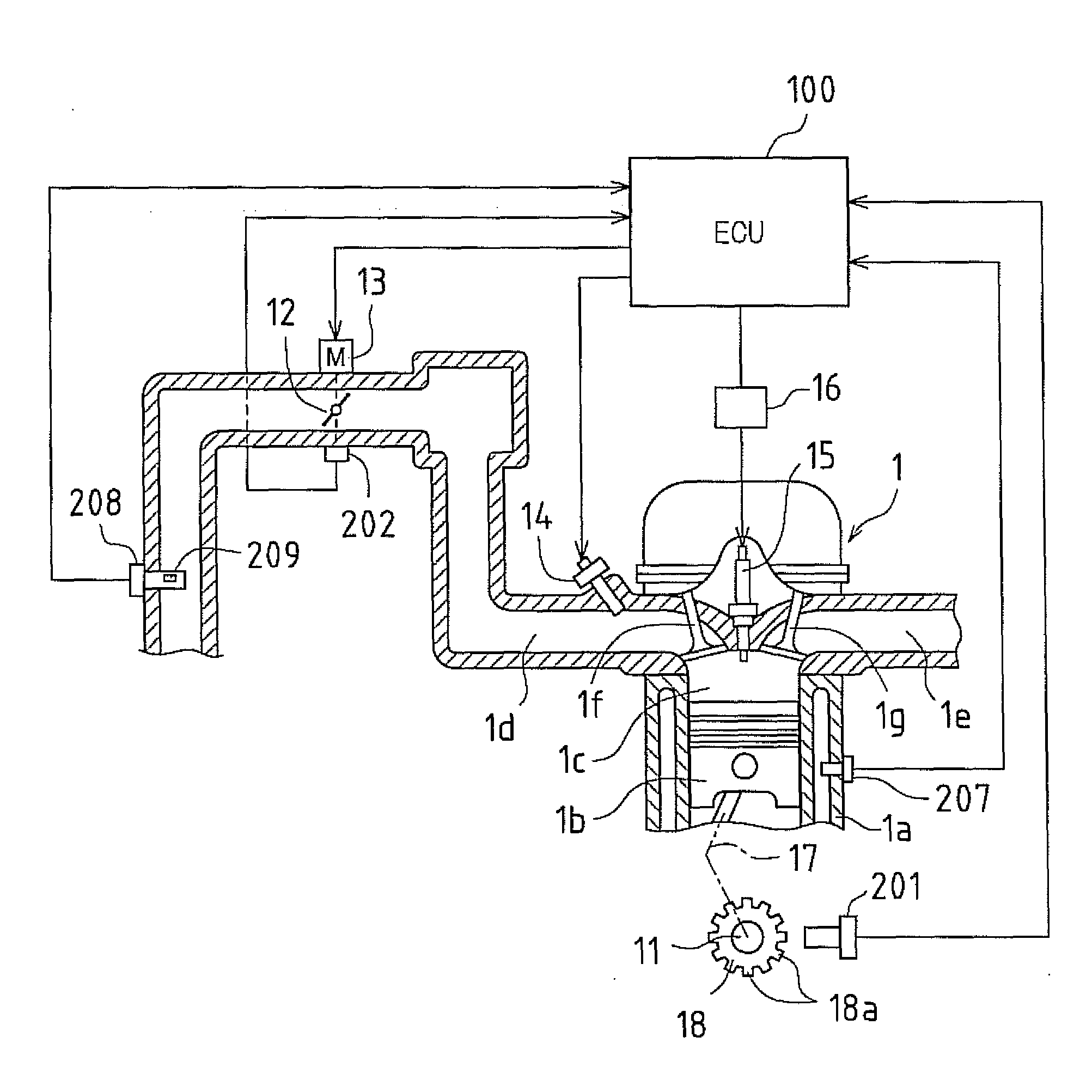
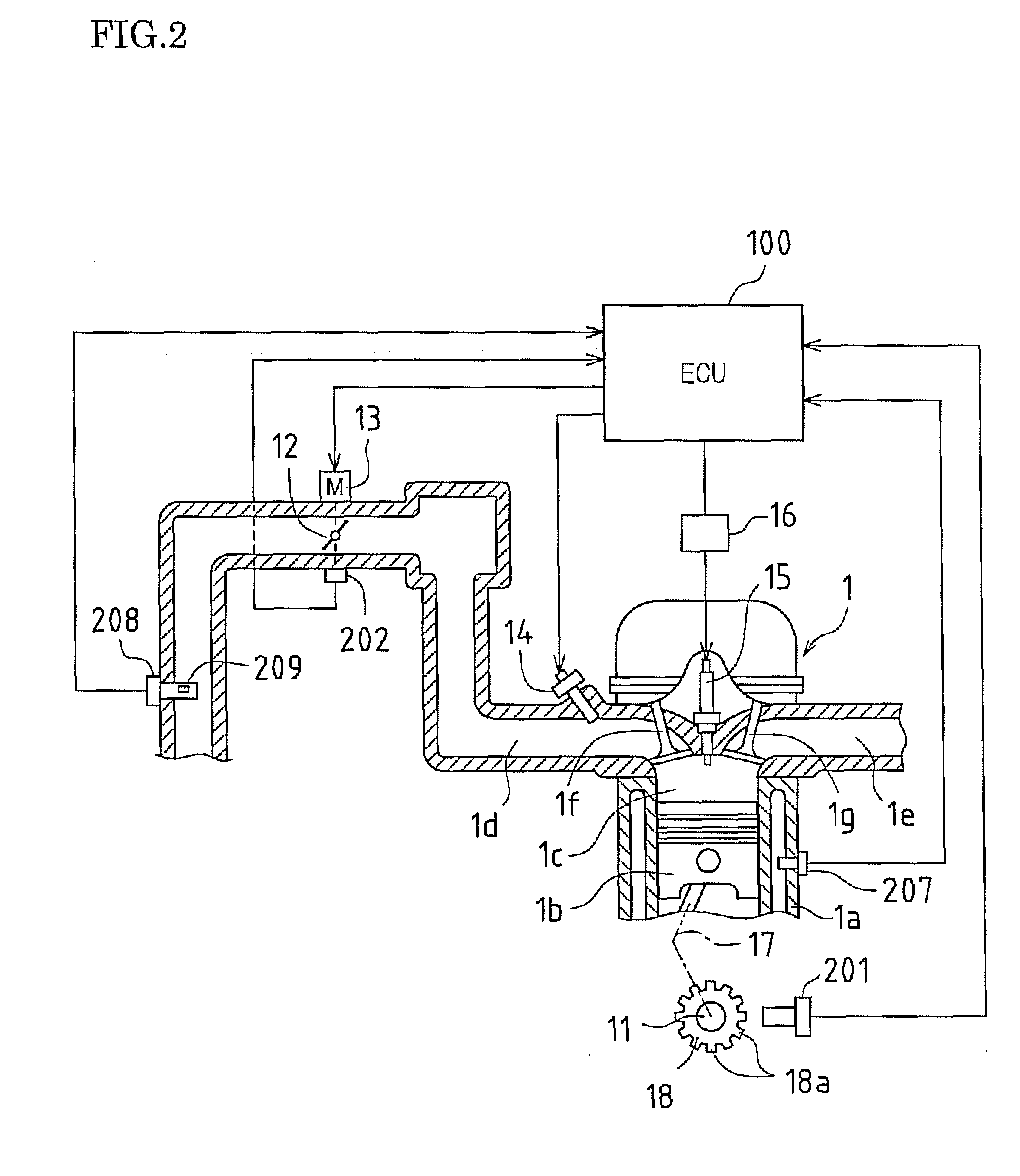
[0058]The engine 1, for example, is a 4-cylinder gasoline engine, and as shown in FIG. 2, is provided with a piston 1b that moves back and forth in the vertical direction within a cylinder block 1a that constitutes each cylinder. The piston 1b is connected to a crank shaft 11 via a connecting rod 17, and back-and-forth movement of the piston 1b i...


PUM


Abstract

When downshift control is performed during fuel cut control (when coast-down gearshift control is performed), fuel cut reset revolutions are lowered and set to revolutions Ndwn that are lower than fuel cut reset revolutions Nnor for normal control. By such a setting, it becomes possible to maintain fuel cut control and deceleration lockup slippage control even when engine revolutions NE temporarily drop during execution of coast-down gearshift control, so an improvement in fuel consumption can be achieved. Moreover, it becomes unnecessary to set a downshift gearshift line to a higher vehicle speed side, so fuel cut can be maintained while suppressing the occurrence of a gearshift shock.

Description

CROSS REFERENCE TO RELATED APPLICATION[0001]This application claims priority under 35 U.S.C. §119(a) on Patent Application No. 2008-299329 filed in Japan on Nov. 25, 2008, the entire contents of which are herein incorporated by reference.BACKGROUND OF THE INVENTION[0002]The present invention relates to a vehicle control apparatus equipped with an engine (internal combustion engine) and an automatic transmission.[0003]In a vehicle equipped with an engine, as a transmission that appropriately transmits torque and revolutions generated by the engine to drive wheels according to the running state of the vehicle, an automatic transmission is known that automatically optimally sets a gear ratio between the engine and the drive wheels.[0004]Examples of an automatic transmission mounted in a vehicle include a planetary gear transmission that sets a gear using frictionally engaging elements such as a clutch and a brake and a planetary gear apparatus, and a belt-driven stepless transmission (...

Claims


Application Information

Patent Timeline
Patent Type & Authority Applications(United States)
IPC IPC(8): F02D41/30G06F19/00B60W10/04B60W10/06B60W10/10B60W10/11F02D29/02F02D41/12F16H59/18F16H59/24F16H59/34F16H59/42F16H59/44F16H59/74F16H61/08F16H61/10F16H61/68F16H61/682F16H63/50
CPCF02D31/007F02D2400/12F02D41/126F02D41/023
Inventor AYABE, ATSUSHIASAMI, TOMOHIRO
Owner TOYOTA JIDOSHA KK
Why Eureka
Try Eureka