
Method and system for providing and installing photovoltaic material

Inactive Publication Date: 2010-06-03
HECKEROTH STEVE +2
View PDF5 Cites 16 Cited by
  • Summary
  • Abstract
  • Description
  • Claims
  • Application Information

AI Technical Summary

Benefits of technology

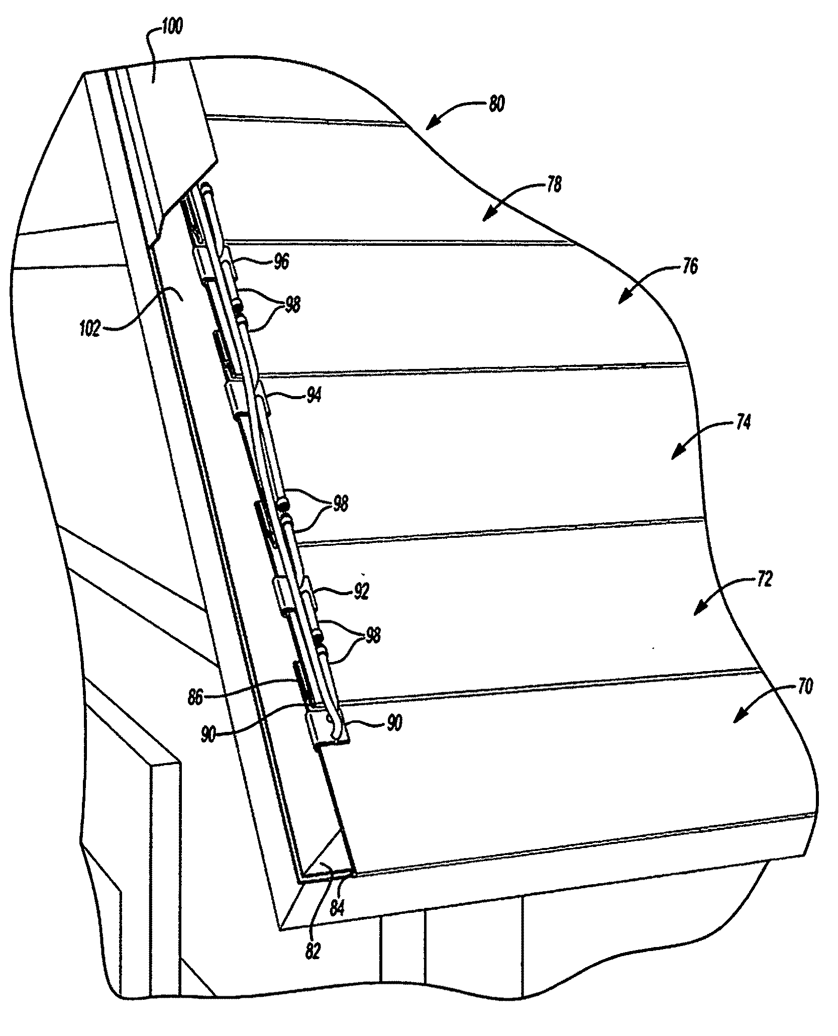
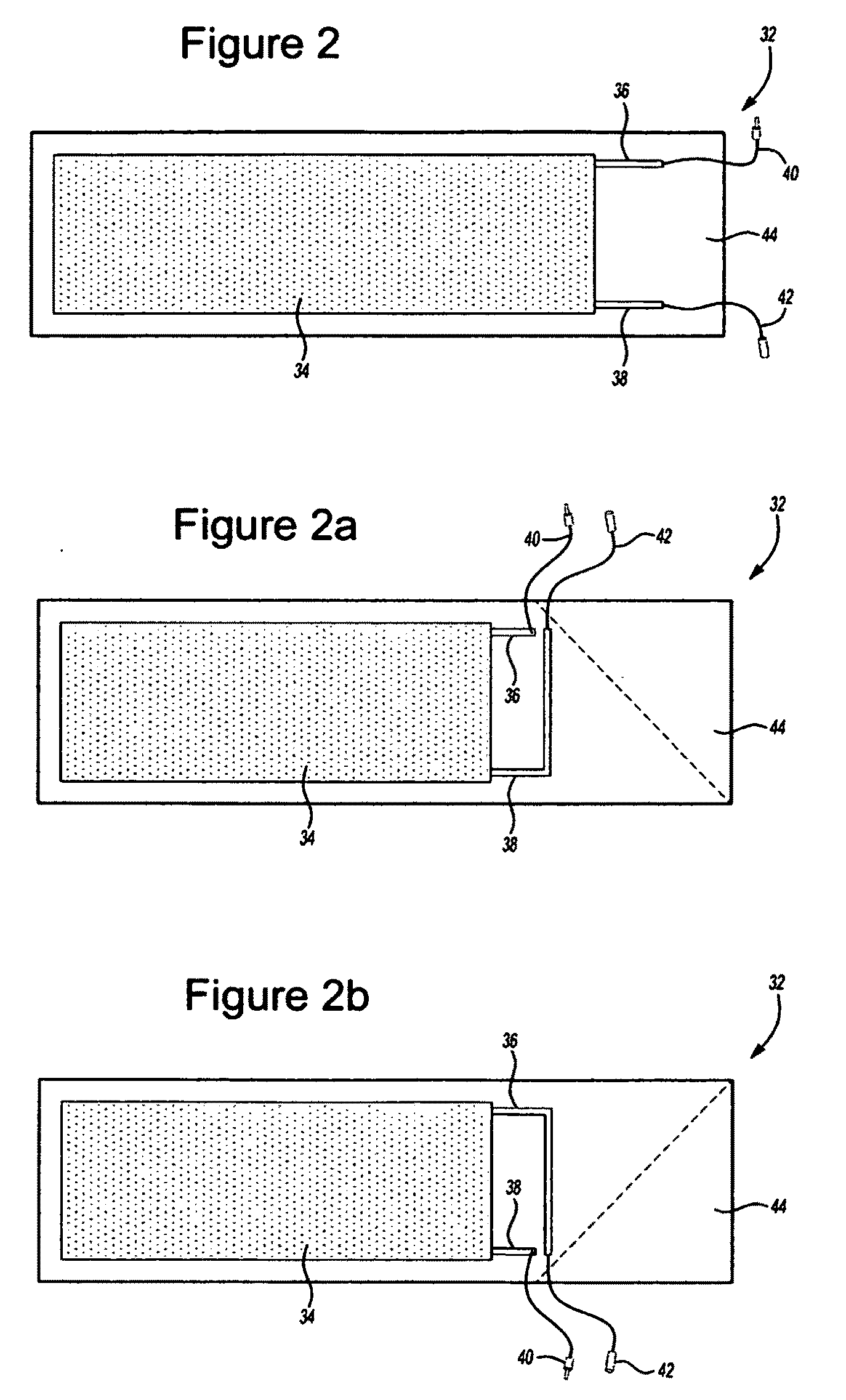
[0014]The present invention may also provide electrical connection clamp and electrical wiring members that can be easily attached to said electrically active contact points on said photovoltaic strips such that said photovoltaic strips can be connected in series, parallel, series parallel, or to combiner box, or battery, or power conditioning equipment, and that said electrical connection members may terminate at a location on said surface of any pitch or angle that is easily serviced, made weatherproof, and can be finished covered in an aesthetically pleasing manner.

Problems solved by technology

Early renewable energy installations, including PV, were used to power remote facilities when the cost of extending utility service was not practical.
Utility scale ground mount PV installations cover valuable land and require transmission and distribution infrastructure.
Utility ground mount requires a costly permitting process and security infrastructure.
Even with government incentives, the rising cost of conventional power and the mounting evidence of the irreversible damage done by continued fossil fuel combustion, a very small percentage of consumers have so far been willing to install renewable energy systems.
The high initial investment and the perceived objectionable aesthetic of PV modules are the reasons most often given for not installing a PV system.
Unfortunately, the finished thin and flexible PV products are currently only available in a few specific sizes and must be bonded over traditional roofing products.
Furthermore, the installation cost of the PV products currently available requires a substantial investment by the consumer.

Method used


Image

  • Method and system for providing and installing photovoltaic material
  • Method and system for providing and installing photovoltaic material
  • Method and system for providing and installing photovoltaic material

Examples


Embodiment Construction

[0035]As required, a detailed description of the present invention is disclosed herein; however, it is to be understood that the disclosed description is merely exemplary of the invention that may be embodied in various and alternative forms. The figures are not necessarily drawn to scale. Some features may be exaggerated or minimized to show details of particular components. Therefore, specific structural and functional details disclosed herein are not to be interpreted as limiting, but merely as a representative basis for the claims and / or as a representative basis for teaching one skilled in the art to variously employ the present invention.

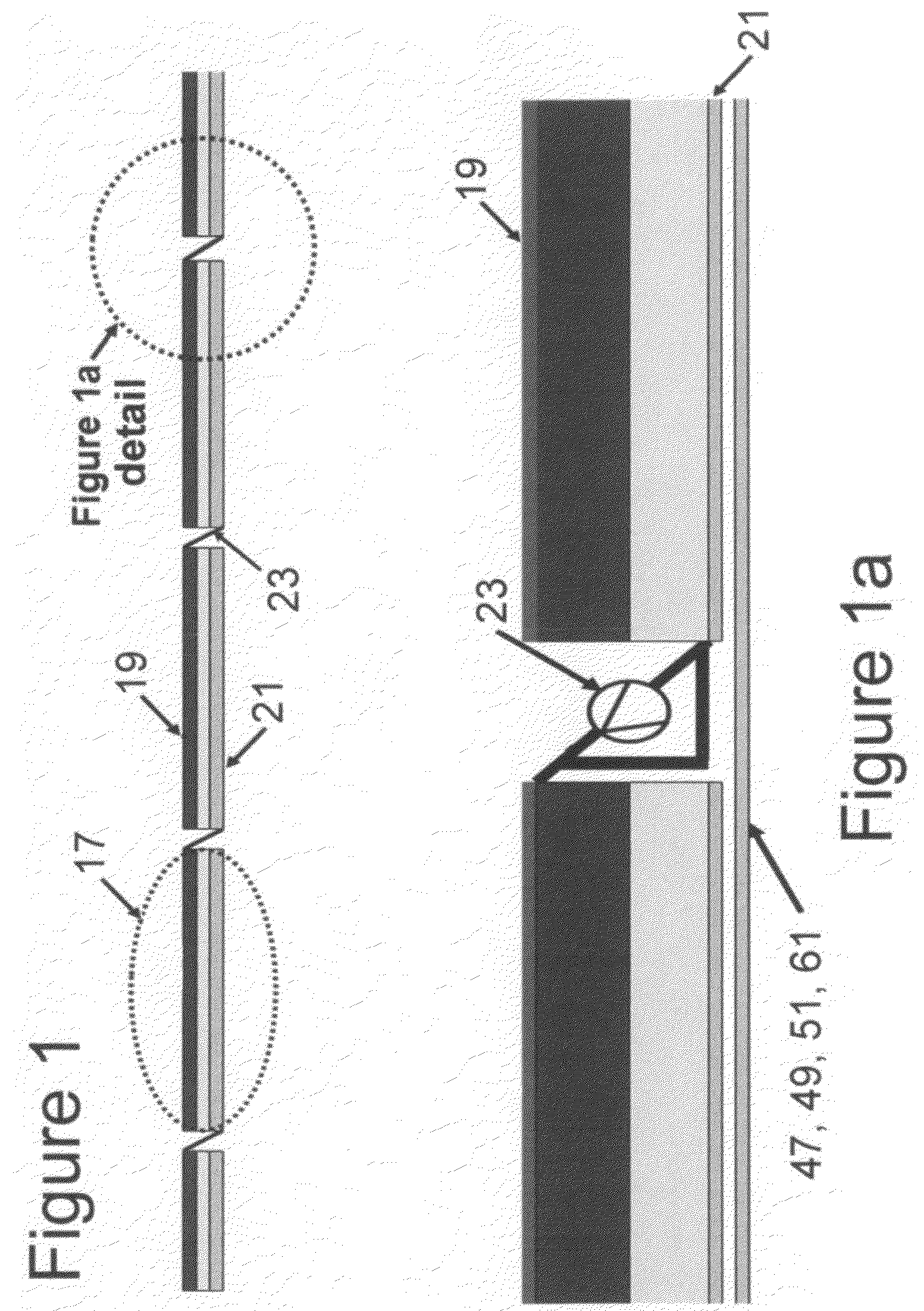
[0036]As disclosed in FIG. 1, one or more embodiments of the present disclosure will incorporate photovoltaic (PV) cells 17 that may be constructed of a thin-film semiconductor material deposited on a thin flexible substrate. The thin-film semiconductor material may include a body of substrate and electrode materials having a number of layers ...


PUM


Abstract

The present invention discloses a flexible building integrated photovoltaic energy absorbing system and method that comprise variable length photovoltaic strips which can be applied to a surface of a building at any pitch or angle. Further, the present invention may include electrical connection members that can be easily attached to said photovoltaic strips at any point on their surface such that said photovoltaic strips can be connected in series, parallel, series parallel, or any other electrical combination, and that said electrical connection members may terminate at a location on said surface of any pitch or angle that is easily serviced, made weatherproof, and can be finished covered in an aesthetically pleasing manner.

Description

FIELD OF THE INVENTION[0001]One or more embodiments of the present disclosure relate to a method and system for providing and installing a photovoltaic (PV) material onto the surface of a building.BACKGROUND ART[0002]Early renewable energy installations, including PV, were used to power remote facilities when the cost of extending utility service was not practical. These types of renewable energy installations are generally referred to as off-grid and may include batteries to provide power when renewable energy is not available.[0003]Batteries are typically available in nominal 12 volt, direct current (DC) increments and must be charged at a DC voltage that is slightly higher than this nominal DC voltage. For this reason a specific number of PV cells were electrically connected in series and encapsulated into a module.[0004]Within the last several years, governments and consumers have begun to recognize the benefits of increased renewable energy production to reduce dependence on fi...

Claims


Application Information

Patent Timeline
IPC IPC(8): E04B1/38H01L31/042
CPCY02B10/12H02S20/23H02S30/20H02S40/36Y02E10/50Y02A30/60Y02B10/10
Inventor HECKEROTH, STEVEPERKINS, DANIEL M.LETOVSKY, HOWARD
Owner HECKEROTH STEVE
Learn More