Self sealing bag in box cap assembly

a self-sealing bag and box cap technology, applied in the field of cap assembly, can solve the problems of increasing the cost of use of such a system, each of which is susceptible to failure, and achieve the effect of improving the service life of the system

Active Publication Date: 2010-06-03
SCHOLLE IPN CORP
View PDF6 Cites 28 Cited by
  • Summary
  • Abstract
  • Description
  • Claims
  • Application Information

AI Technical Summary

Benefits of technology

[0011]The retaining ring includes a tab, a sealing membrane engagement surface and an inner wall structure opposite the sealing membrane engagement surface. The retaining ring is positioned with the sealing membrane engagement surface in overlying engagement with the sealing membrane. Extension of the tab into the recessed circumferential channel of the body releasably maintains said overlying engagement and biases the retaining ring against the membrane. The inner wall structure of the retaining ring extends radially inward beyond the membrane engaging flange of the sealing membrane, to in turn, protect the membrane.

Problems solved by technology

Among other drawbacks, such a system requires many separate components which increase the cost of use of such a system.
Additionally, with such a system, many connections are utilized, each of which is susceptible to failure.

Method used


Image

  • Self sealing bag in box cap assembly
  • Self sealing bag in box cap assembly
  • Self sealing bag in box cap assembly

Examples


Embodiment Construction

[0022]While this invention is susceptible of embodiment in many different forms, there is shown in the drawings and described herein in detail a specific embodiment with the understanding that the present disclosure is to be considered as an exemplification and is not intended to be limited to the embodiment illustrated.

[0023]It will be understood that like or analogous elements and / or components, referred to herein, may be identified throughout the drawings by like reference characters. In addition, it will be understood that the drawings are merely schematic representations of the invention, and some of the components may have been distorted from actual scale for purposes of pictorial clarity.

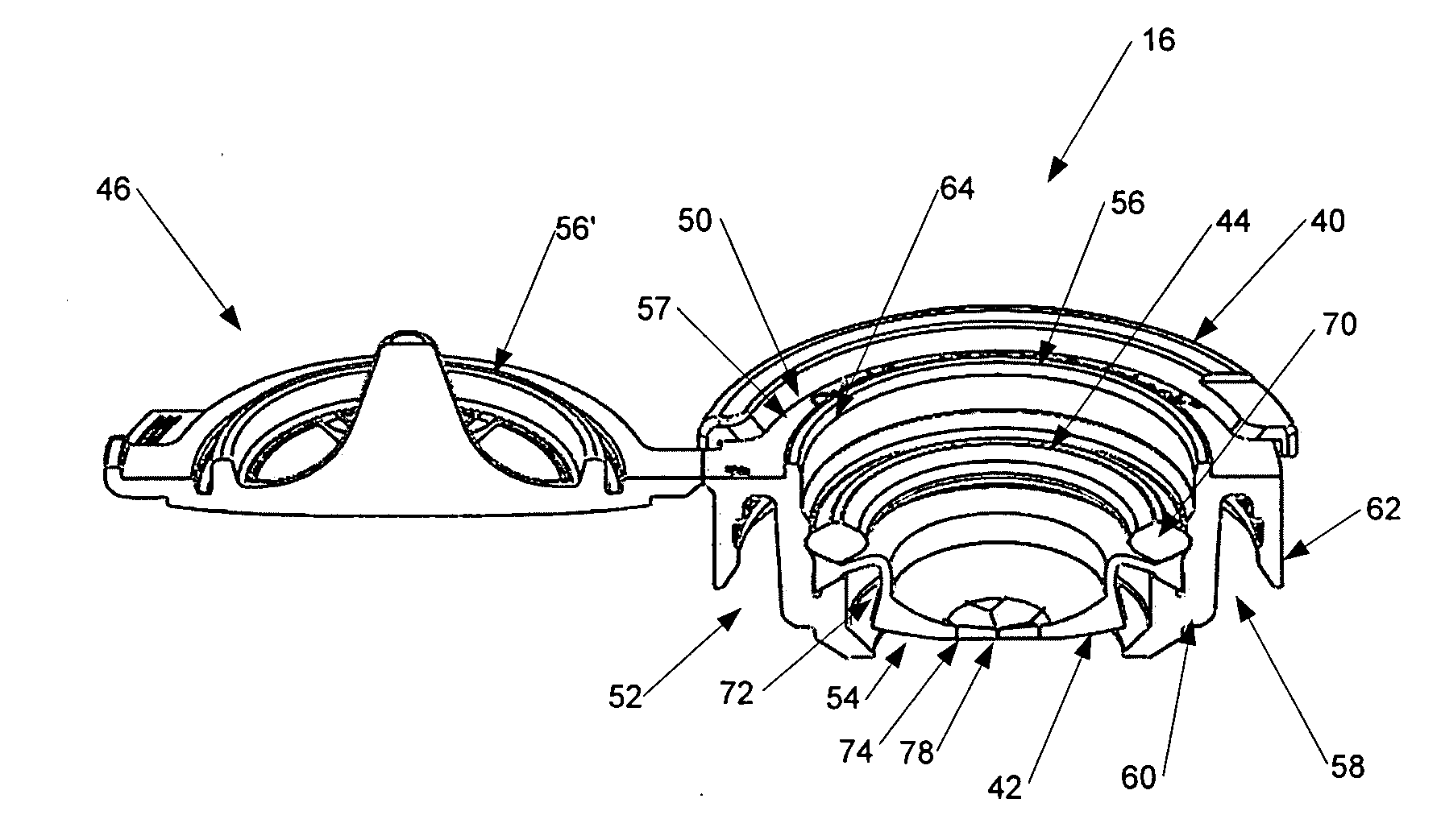
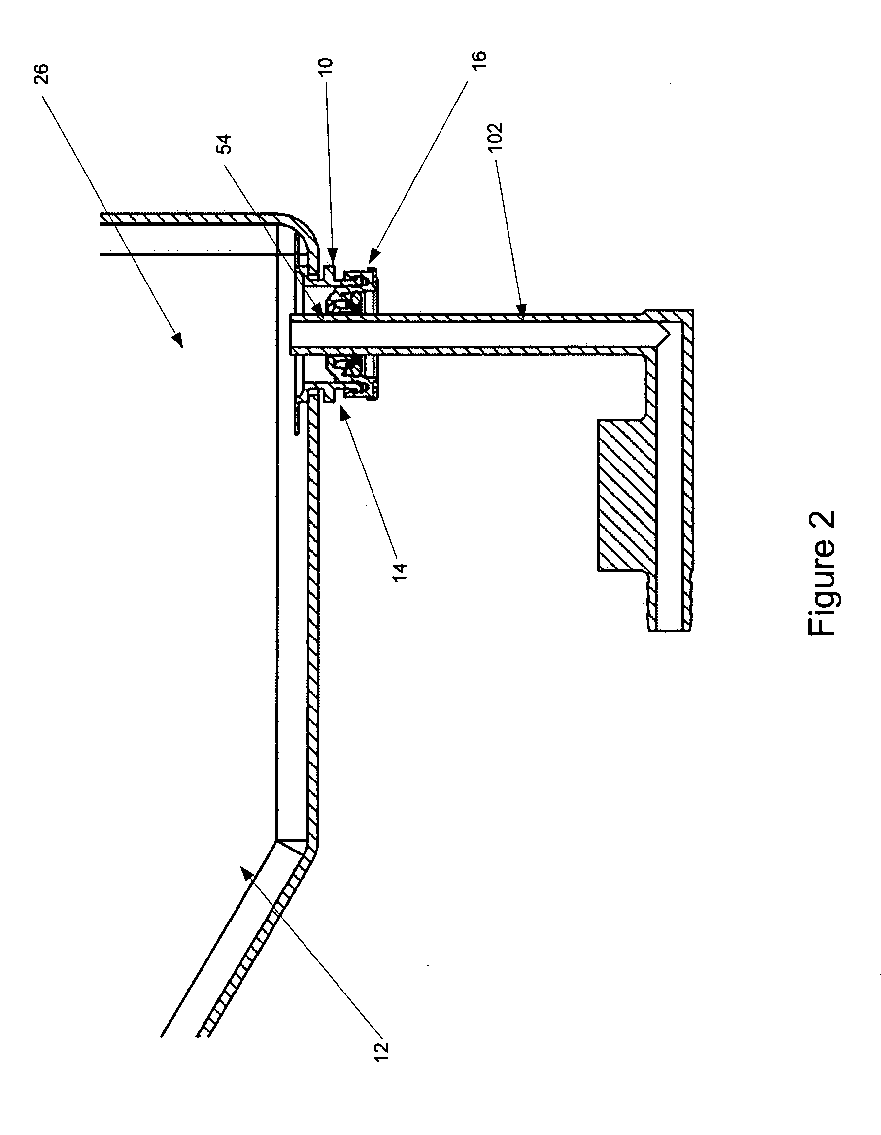
[0024]Referring now to the Figures, and in particular to FIG. 2, container assembly 10 includes container body 12, spout 14 and cap assembly 16. Container body 12 comprises a plurality of panels and a plurality of seals. The panels and seals cooperate to define cavity 26. Of course, the inven...


PUM

PropertyMeasurementUnit
acute angleaaaaaaaaaa
wall structureaaaaaaaaaa
acute angleaaaaaaaaaa

Abstract

A cap assembly comprising a body, a sealing membrane and a retaining ring. The body includes a top surface, a bottom surface. A spout engagement channel is positioned on the bottom surface. An opening is provided through the body and includes a recessed circumferential channel and a membrane engaging flange positioned proximate the recessed circumferential channel. The sealing membrane covers the opening and includes a body engaging flange and a pierceable surface. The sealing membrane is positioned upon the membrane engaging flange so that the body engaging flange and the membrane engaging flange are in overlying engagement. The retaining ring includes a tab, a sealing membrane engagement surface and an inner wall structure opposite the sealing membrane engagement surface. The retaining ring is positioned with the sealing membrane engagement surface in overlying engagement with the sealing membrane. Extension of the tab into the recessed circumferential channel of the body releasably maintains said overlying engagement and biases the retaining ring against the membrane. The inner wall structure of the retaining ring extends radially inward beyond the membrane engaging flange of the sealing membrane, to in turn, protect the membrane.

Description

CROSS-REFERENCE TO RELATED APPLICATION[0001]This application claims priority from U.S. Pat. App. Ser. No. 61 / 196,969, filed Oct. 22, 2008, entitled “Self Sealing Bag in Box Cap Assembly”, the entire disclosure of which is hereby incorporated by reference.BACKGROUND OF THE DISCLOSURE[0002]1. Field of the Disclosure[0003]The disclosure relates in general to a cap assembly, and more particularly, to a self sealing bag in box cap assembly. Such a cap assembly is used in association with the dispensing of flowable material from a bag.[0004]2. Background Art[0005]Self sealing bags have become increasingly useful, especially in the food packaging industry. One current system utilizes a flexible bag having a spout to which a Sentry cap available from Scholle Corporation is affixed. A separate hose is provided which has at a first end a probe and at a second end a connector available from Erie Plastics with a flexible membrane. One such membrane is available from LMS of Illinois. The probe i...

Claims


Application Information

Patent Timeline
Patent Type & Authority Applications(United States)
IPC IPC(8): B65D41/02B65D53/00
CPCB65D47/0838B65D41/205B65D2231/022B65D75/5877B65D53/02
Inventor THURMAN, CHARLESARCH, JAMES J.
Owner SCHOLLE IPN CORP
Why Eureka
Try Eureka