Inhomogeneous lens with maxwell's fish-eye type gradient index, antenna system and corresponding applications

a gradient index, fish-eye type technology, applied in the field of lens-type focusing systems, can solve the problems of difficult to strictly follow this law when producing lenses, high production cost, and mechanical complexity of last techniques, and achieve the effect of good radiation properties and low permittivity

Inactive Publication Date: 2010-06-03
UNIV DE RENNES I
View PDF4 Cites 6 Cited by
  • Summary
  • Abstract
  • Description
  • Claims
  • Application Information

AI Technical Summary

Benefits of technology

[0047]Thus, unlike the alternative consisting of using a printed antenna array, with a single source antenna of this type, the dielectric losses are absent and the directivity of this type of antenna (patch) is very significant (9-10 dBi) due to the very low permittivity of the substrate (air). Moreover, this solution makes it possible to obtain very good radiation properties (openings, lobes, directivity) by comparison with the solution involving a source array.
[0048]In an advantageous embodiment of the invention, the focal spot of said lens is used due to the fact that the index distribution obtained with said concentric shells is discrete. This focal spot is located outside the lens and at a predetermined distance h from the lens. For this, the system also includes means for de-centering said at ...

Problems solved by technology

It is therefore impossible to strictly follow this law when producing the lens.
However, this last technique is also mechanically complex becaus...

Method used


Image

  • Inhomogeneous lens with maxwell's fish-eye type gradient index, antenna system and corresponding applications
  • Inhomogeneous lens with maxwell's fish-eye type gradient index, antenna system and corresponding applications
  • Inhomogeneous lens with maxwell's fish-eye type gradient index, antenna system and corresponding applications

Examples


first embodiment

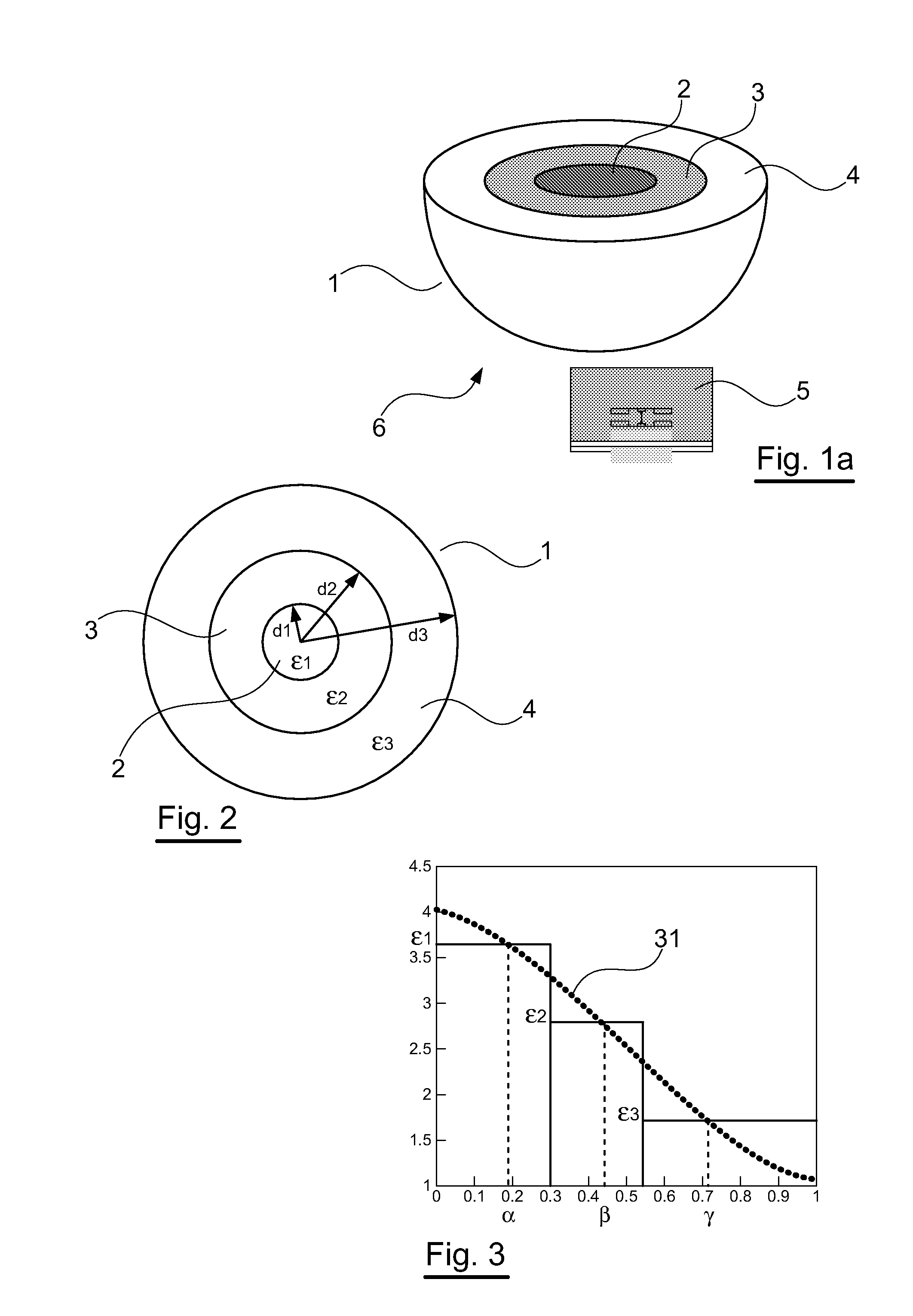
[0106]An example of a complete structure 6 mentioned above (combination of the antenna array 5 above with the Maxwell's fish-eye lens 1 according to the first line of the table above) was simulated with the 3D CST Microwave Study software (registered trademark) (based on the finite-difference time-domain method), and then measurements were taken.

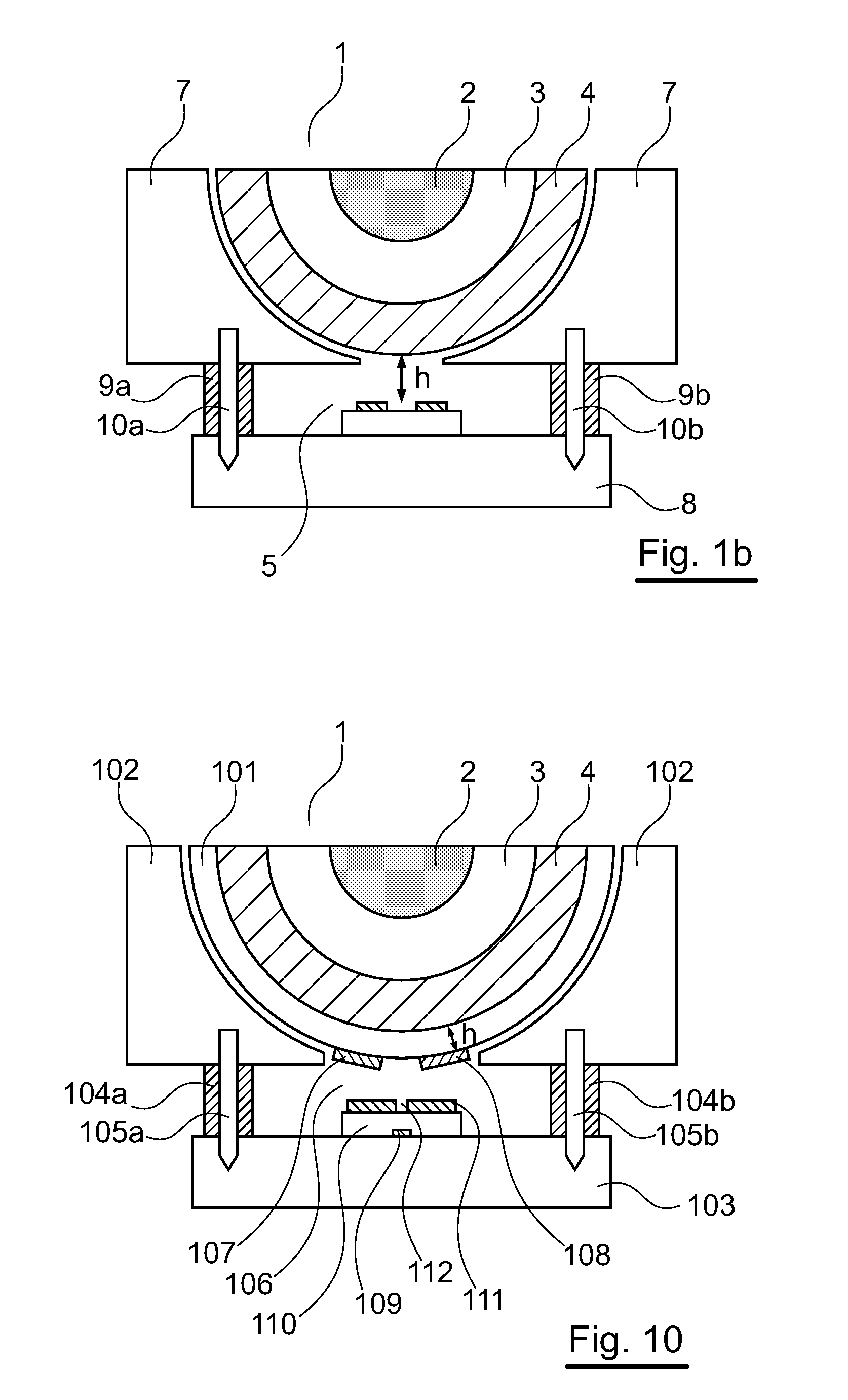
[0107]A number of simulations of this antenna structure 6 example were performed by changing the distance h between these two elements so as to show the importance of this parameter. It is clear that the directivity can be quasi-stable on the frequency band considered if h is equal to 2.5 mm. Indeed, as the dielectric constant distribution is not continuous in the lens 1, the source array 5 cannot be found on the lens, but at a distance h substantially equal to the distance at which the focusing of the lens is done outside of the lens (see the description of FIGS. 4a, 4b, 5a and 5b above). This makes it possible to optimize the directivity ...

second embodiment

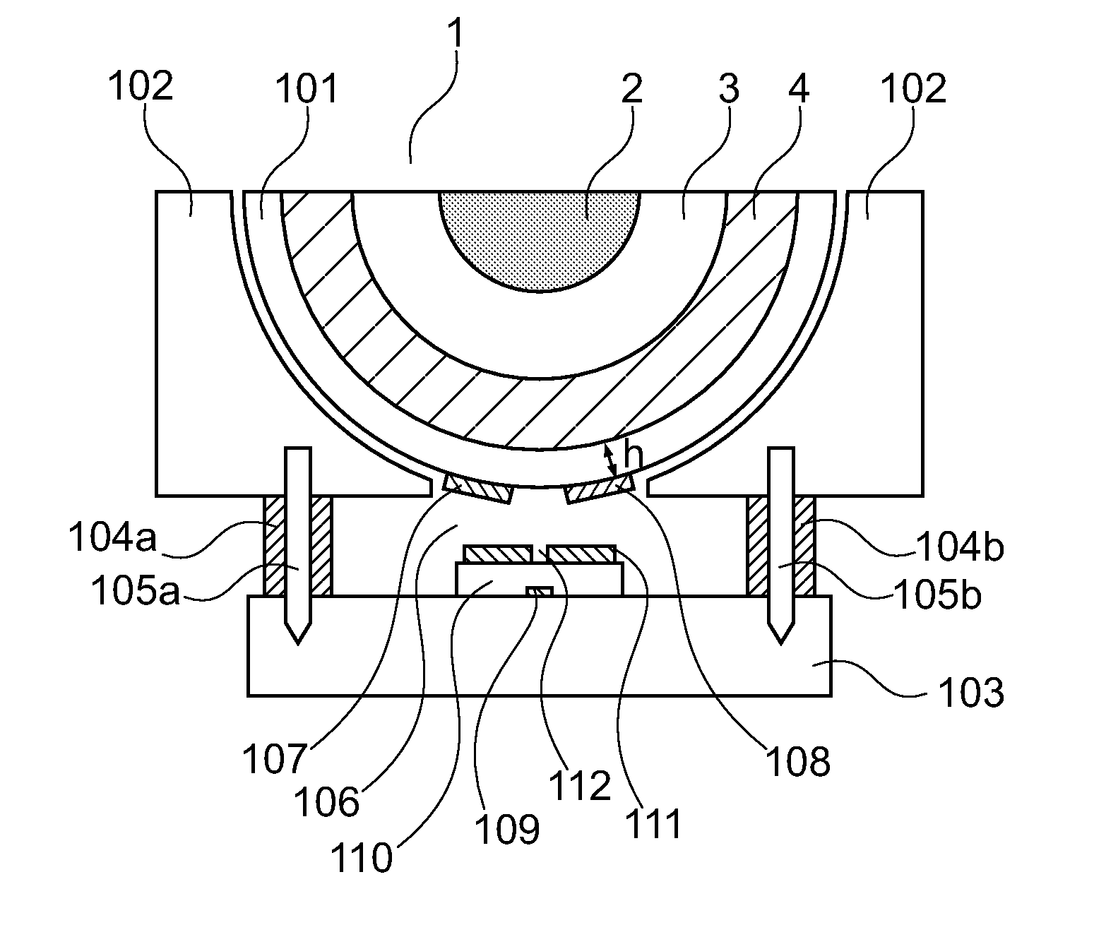
[0128]In this second embodiment, the means for positioning the lens 1 with respect to the printed antenna array 106 include:

[0129]an additional shell 101, having a shape fitting the external surface of the lens 1, made with a substrate of which the dielectric permittivity approximates that of air, and which can be metallized (so as to be capable of receiving one or more radiating patches);

[0130]a support (or base) 102 made of a foam material (of which the dielectric permittivity approximates that of air), and in which the lens 1 is embedded, surrounded by the additional shell 101;[0131]a metal base 103;[0132]spacers 104a, 104b made of a foam material and making it possible to maintain a predetermined distance (not to be confused with the height h, as explained below) between the lens 1 and the metal base 8; and[0133]screws 105a, 105b for assembling the support 102, the metal base 103 and the spacers 104a, 104b.

[0134]The printed antenna array 106 is the type presented above in relat...


PUM


Abstract

The invention concerns an inhomogeneous lens with Maxwell's Fish-eye type gradient index (1), made in the shape of a hemisphere. The invention is characterized in that the lens comprises N hemispheric concentric shells (2 to 4), with different discrete dielectric constants and mutually interlaced without void between the two successive shells, with 3≦N≦20, the discrete dielectric constants of the N shells being such that they define a discrete distribution close to the theoretical distribution of the index inside the lens.

Description

CROSS-REFERENCE TO RELATED APPLICATIONS[0001]This Application is a Section 371 National Stage Application of International Application No. PCT / EP2006 / 063912, filed Jul. 5, 2006 and published as WO 2007 / 003653 A1 on Jan. 11, 2007, not in English.FIELD OF THE DISCLOSURE[0002]The field of the disclosure is that of lens-type focusing systems, which can be used at hyperfrequencies and in particular at millimeter waves.[0003]More specifically, the disclosure relates to an inhomogeneous lens with a gradient index, of the Maxwell's fish-eye type.[0004]The disclosure also relates to an antenna system combining such a lens with one or more source antennas.[0005]The disclosure has numerous applications, such as, for example, high-speed satellite communications, digital satellite television, anti-collision radar applications in motor vehicles, etc.[0006]In the case of the first application mentioned above, namely high-speed satellite communications, the antenna system according to the disclosur...

Claims


Application Information

Patent Timeline
IPC IPC(8): H01Q19/06H01Q15/02
CPCH01Q19/062H01Q19/06
Inventor LAFOND, OLIVIERHIMDI, MOHAMEDRONDINEAU, SEBASTIENFUCHS, BENJAMIN
Owner UNIV DE RENNES I
Why Eureka
Try Eureka