Combustor

a technology of combustor and cylinder, which is applied in the field of combustor, can solve the problems of pilot burner burnout, and achieve the effects of avoiding any possible burnout of the pilot burner, compact assembly, and reducing the amount of nox emitted

Active Publication Date: 2010-06-03
KAWASAKI HEAVY IND LTD
View PDF27 Cites 17 Cited by
  • Summary
  • Abstract
  • Description
  • Claims
  • Application Information

AI Technical Summary

Benefits of technology

[0015]The pilot burner referred to above may include a pre-mixing member provided in a pre-mix gas passage defined in the pilot burner, and having a multiplicity of pores defined therein for facilitating mixing of fuel and air. The presence of the pre-mix gas passage of a kind having the multiplicity of pores defined therein is effective in that the pre-mix gas of fuel and air, then flowing through the pre-mix gas passage in the pilot burner, produces a turbulent flow as it pass through a pre-mixing member and the fuel and the air can therefore be more uniformly mixed together, and, therefore, the amount of NOx emitted can be further reduced.
[0016]Where the pilot burner also employs the pre-mix combustion system as hereinabove described, it is preferred that the main burner has an annular pre-mix gas passage defined therein and the pre-mix gas passage of the pilot burner is arranged inwardly of an inner periphery of the annular pre-mix gas passage of the main burner. This is particularly advantageous in that the pre-mix gas passage of the pilot burner can be employed by the effective utilization of a space available inwardly of the annular pre-mix gas passage of the main burner, and, therefore, the combustor can be assembled compact in size.
[0017]In another embodiment of the present invention, the pilot burner may be adapted to inject the pre-mix gas at an initial velocity higher than a velocity of propagation of flame so as to form a flame holding region, at which the velocity of flow of the pre-mix gas is reduced down to a value equal to the velocity of propagation of flame, at a location spaced from the pilot burner in a direction axially of the pilot burner. By so doing, any possible burnout of the pilot burner can be avoided assu

Problems solved by technology

It has, however, been found that the related art combustor utilizing the swirling type pilot burner 84 discussed above has some problems, which will now be discuss

Method used


Image

  • Combustor
  • Combustor
  • Combustor

Examples


Embodiment Construction

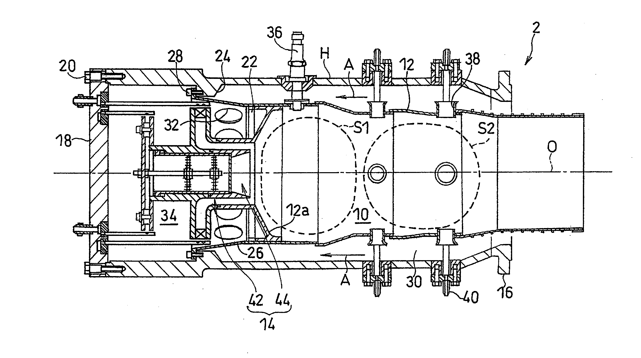
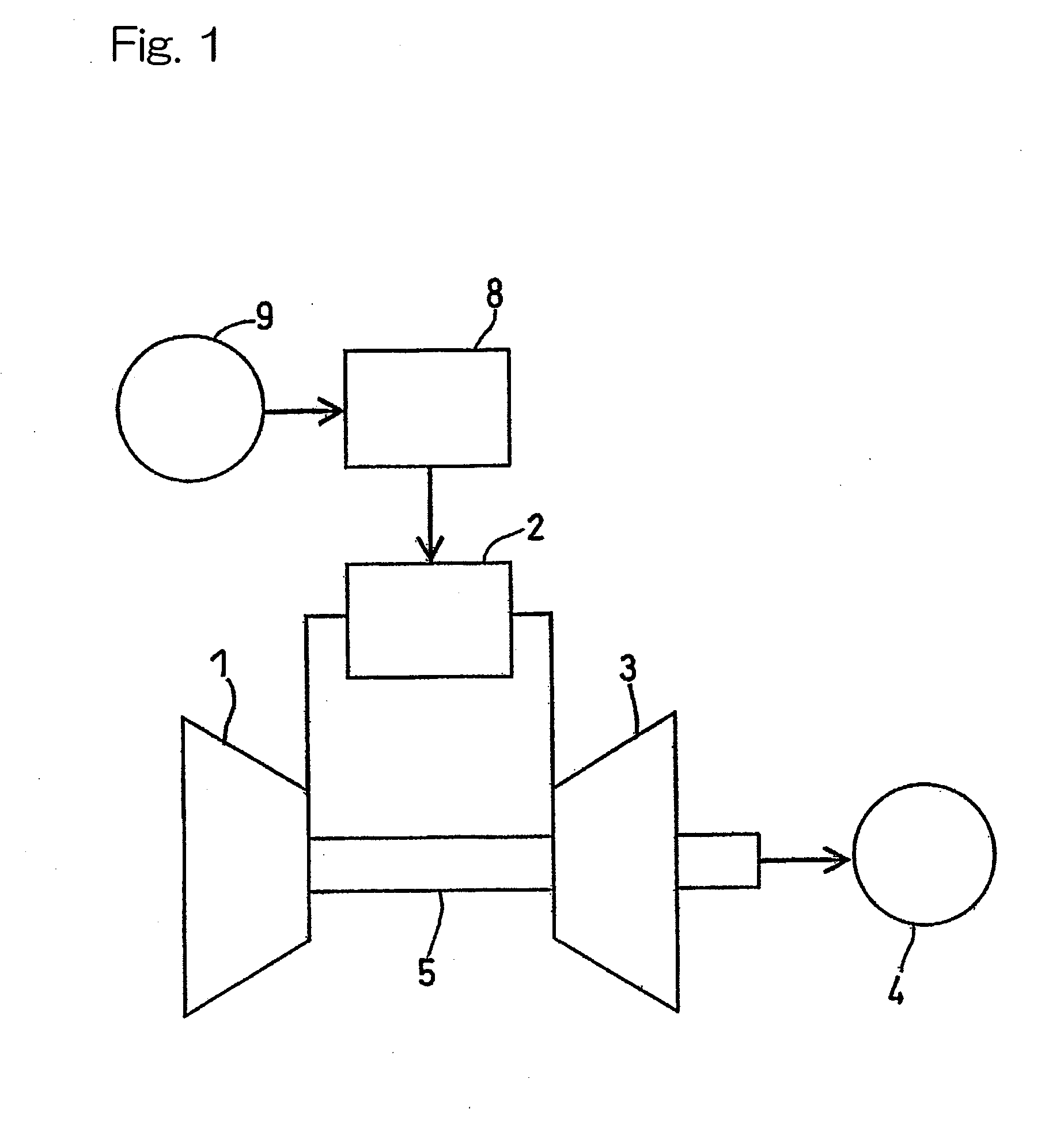
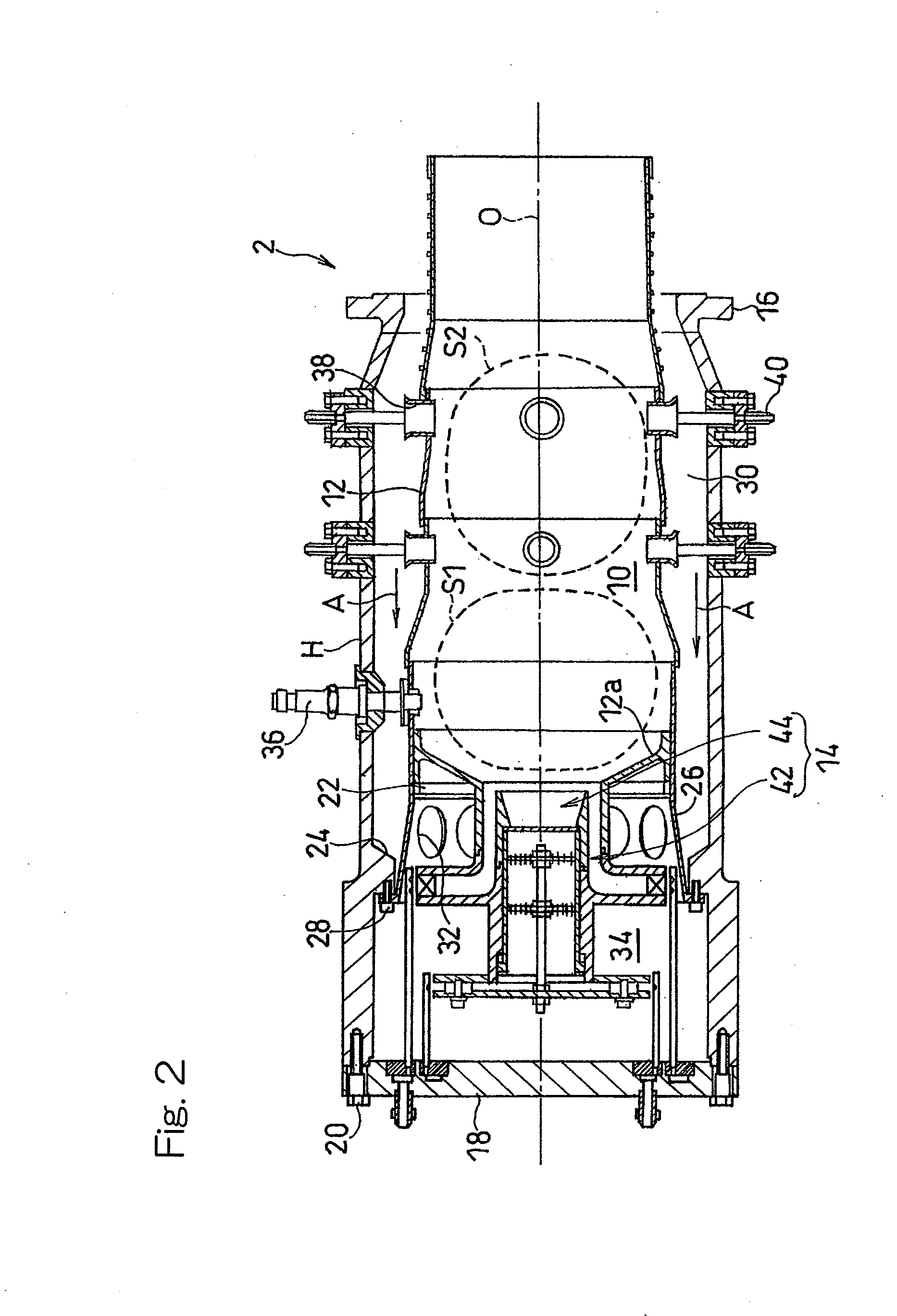
[0028]Embodiments of the present invention will be described in detail with particular reference to the accompanying drawings. In particular, FIG. 1 illustrates a schematic diagram showing a gas turbine engine, in which a combustor according to a first embodiment of the present invention is adopted. The gas turbine engine GT shown therein has three principal components including a compressor 1, a combustor 2 and a turbine 3, all of which are so operatively linked that a compressed air supplied from the compressor 1 is burned within the combustor 2 to generate a high pressure combustion gas that is subsequently supplied to the turbine 3. The compressor 1 is drivingly coupled with the turbine 3 through a rotary shaft 5 and is therefore driven by the turbine 3. An output from this gas turbine engine GT is utilized to drive a load 4 such as, for example, an aircraft rotor or an electric generator. The combustor 2 is supplied with a fuel from a fuel supply source 9 through a fuel control...


PUM


Abstract

A combustor, in which a flame holding region is formed at a location distant from a pilot burner to avoid burnout of the pilot burner and in which flame holding capability is increased to use a lean pre-mix gas for reducing NOx emission, is provided. The combustor includes a combustion liner having a cylindrical side wall that defines a combustion chamber; and a main burner positioned at a top portion of the combustion liner for injecting an annular pre-mix gas into the combustion chamber to form a reverse flow region at a downstream portion thereof, which region is oriented towards the top portion of the combustion chamber along a longitudinal axis. In this combustor, a pilot burner is arranged at the top portion for injecting a mixture of fuel and air only in a direction confronting the reverse flow region.

Description

CROSS REFERENCE TO THE RELATED APPLICATION[0001]This application is a continuation application, under 35 U.S.C.§111(a), of international application No. PCT / JP2008 / 001989, filed Jul. 25, 2008, which claims priority to Japanese patent application No. 2007-210269, filed Aug. 10, 2007, the disclosure of which is incorporated by reference in its entirety into this application.BACKGROUND OF THE INVENTION[0002]1. Field of the Invention[0003]The present invention relates to a combustor for use in machines and equipments that require a feed of a high temperature gaseous medium to, for example, a gas turbine engine or a boiler.[0004]2. Description of the Related Art[0005]In the field of gas turbine engines, for due consideration to the environmental protection, severe standards have been stipulated on the composition of exhaust gases emitted as a result of combustion taking place therein and, hence, reduction of hazardous substances such as, nitrogen oxides (hereinafter referred to as NOx) i...

Claims


Application Information

Patent Timeline
IPC IPC(8): F23Q9/00
CPCF23C2900/03006F23D2209/10F23D2900/00018F23D2900/14701F23R2900/03343F23R3/286F23R3/343F23R3/44F23R3/26F23D2900/00003
Inventor KASHIHARA, HIROYUKIYOSHINO, YASUSHIMATSUMOTO, KIYOSHIKIMURA, TAKESHIKITAJIMA, JUNICHIHORIKAWA, ATSUSHI
Owner KAWASAKI HEAVY IND LTD
Why Eureka
Try Eureka