Connector

Active Publication Date: 2010-06-03
SUMITOMO WIRING SYST LTD
View PDF11 Cites 9 Cited by
  • Summary
  • Abstract
  • Description
  • Claims
  • Application Information

AI Technical Summary

Benefits of technology

[0027]The projecting plate portion may have a small thickness to meet a demand for miniaturization or the like and hence may be less rigid. Thus, there is a possibility that the projecting plate portion will deform and the holder interlocking portion and the holder locking portion may displace from proper locking positions to reduce locking reliability in the process of mounting the projecting plate p

Problems solved by technology

On the other hand, the bevels do not conform to the corresponding parts of the receptacle if t

Method used


Image

  • Connector
  • Connector
  • Connector

Examples


Embodiment Construction

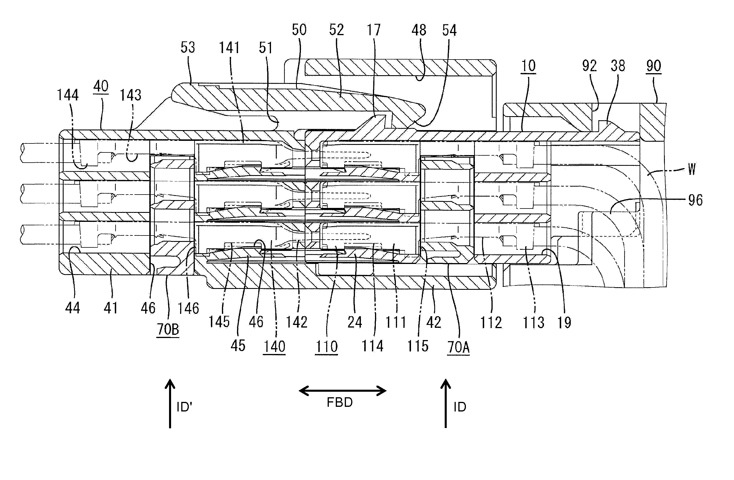
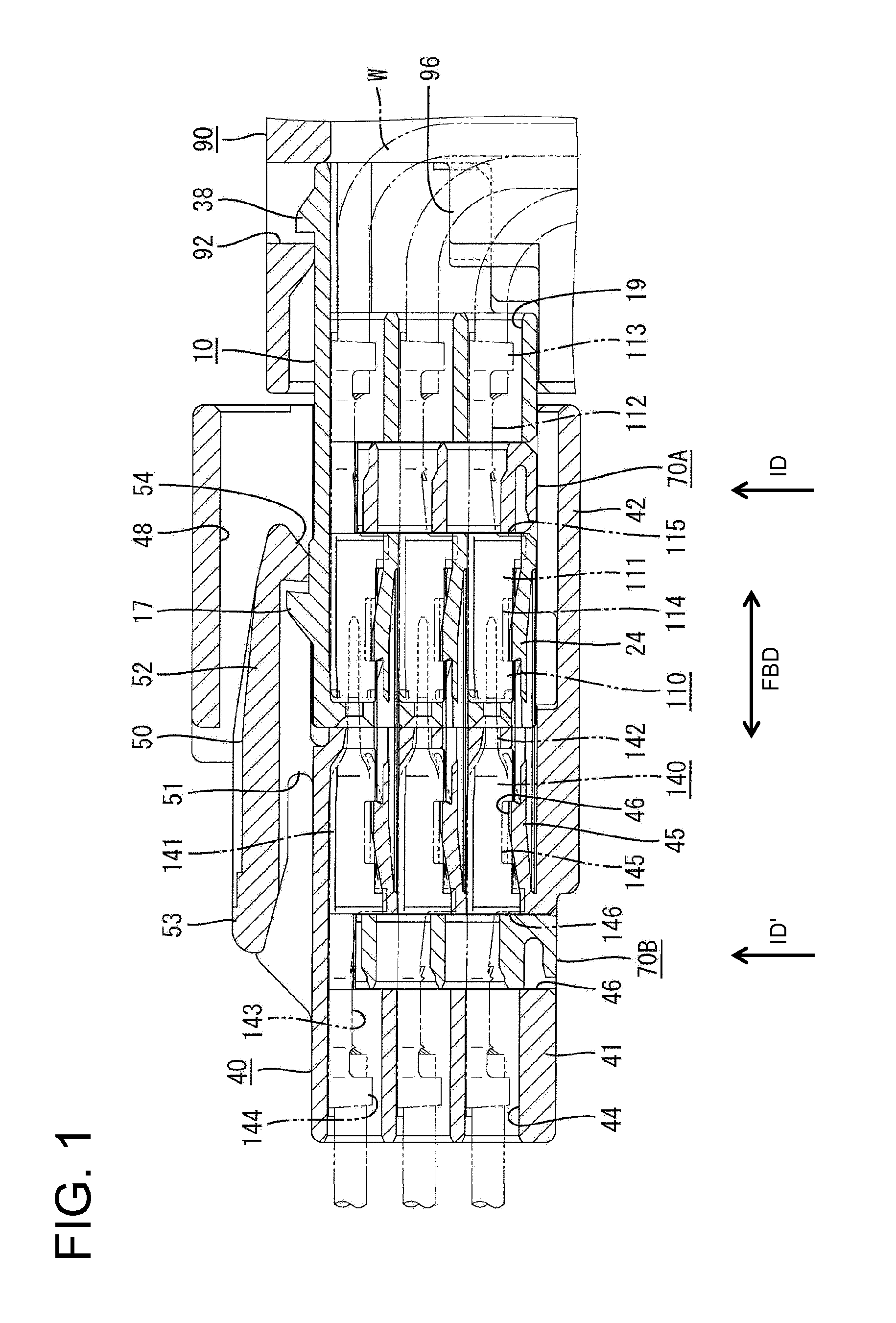
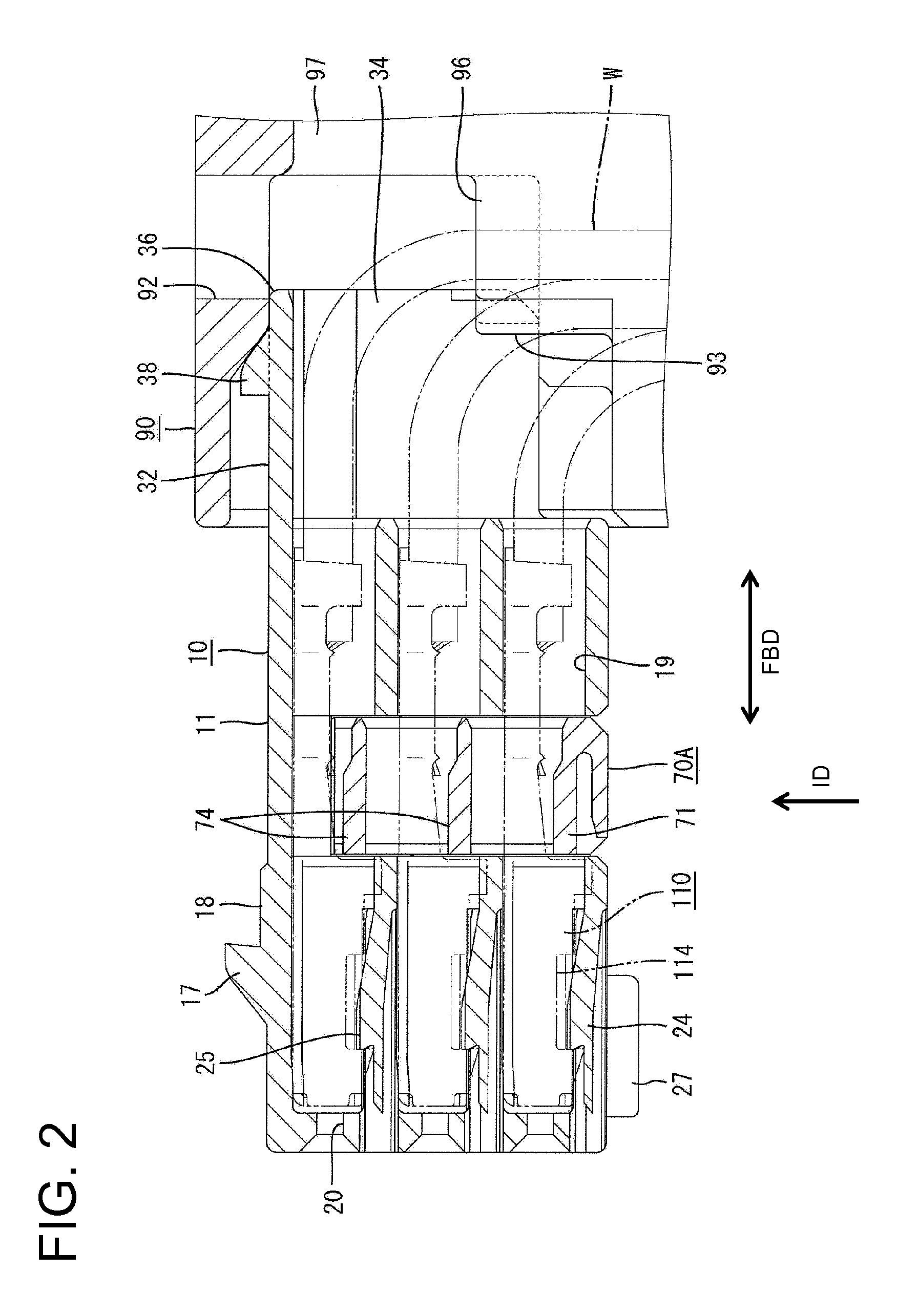
[0049]A connector in according to the invention is described with reference to FIGS. 1 to 20. The connector has a female housing 10 that is connectable with a male housing 40 while being mounted in a holder 90. The holder 90 is provided integrally or unitarily on a mounting object of a vehicle body, such as a door mirror. In the following description, ends of the two housings 10, 40 that are to be connected are referred to as front ends, concerning forward and backward directions FBD, and reference is made to FIG. 1 concerning vertical direction.

[0050]The female housing 10 is made e.g. of synthetic resin and includes a substantially block-shaped housing main body 11. The housing main body 11 has a substantially rectangular cross section with two long parallel sides 12 arranged substantially vertically in FIG. 10 and short parallel upper and lower surfaces 13 arranged substantially in a lateral direction in FIG. 10.

[0051]Corners of the outer surfaces of the housing main body 11 defin...


PUM


Abstract

A connector is provided with a pair of female and male housings (10, 40) connectable with each other. The female housing (10) includes a block-shaped housing main body (11) and the male housing (40) includes a receptacle (42) having an inner surface shape conforming to outer surfaces of the housing main body (11). Corners on the outer surface of the housing main body diagonal to each other are bevels (14, 15) with different shapes. The bevels (14, 15) include moderately inclined portions (14) located at the opposite ends of the upper surface of the housing main body (11) and inclined at a relatively large angle with respect to a height direction and steeply inclined portions (15) located at the opposite ends of the lower surface of the housing main body (11) and inclined at a relatively small angle with respect to the height direction.

Description

BACKGROUND OF THE INVENTION[0001]1. Field of the Invention[0002]The present invention relates to a connector.[0003]2. Description of the Related Art[0004]U.S. Pat. No. 6,206,717 discloses a connector with male and female housings that are connectable with each other. The female housing includes a block-shaped housing main body and the male housing includes a receptacle having an inner surface shaped conforming to outer surfaces of the female housing. A projection is provided on an outer surface of the female housing, and a receiving groove is formed in the male housing. The projection is fit into the receiving groove when the two housings are connected properly. However, the projection contacts the front end edge of the male housing to prevent further connection if the female housing is oriented erroneously, thereby preventing further connection.[0005]The female housing is bulkier than a female housing with no projection by at least as much as a projecting distance of the projection...

Claims


Application Information

Patent Timeline
IPC IPC(8): H01R13/62H01R13/40
CPCH01R13/4223H01R13/4362H01R2201/26H01R13/743H01R13/6272
Inventor MASE, TSUYOSHITANAKA, TSUTOMU
Owner SUMITOMO WIRING SYST LTD
Why Eureka
Try Eureka