Physologically Movable Intervertebral Disc Prosthesis for the Lumbar and Cervical Spine

a technology of intervertebral discs and lumbar spines, which is applied in the field of physically movable intervertebral disc prosthesis for the lumbar and cervical spine, can solve the problems of irritating neural structures, requiring more surgical effort, and damaging the vertebral endplates, so as to achieve optimal lordosis and positioning of sliding areas, the effect of maximizing the load transfer area

Active Publication Date: 2010-06-03
BUETTNER JANZ KARIN +1
View PDF44 Cites 20 Cited by
  • Summary
  • Abstract
  • Description
  • Claims
  • Application Information

AI Technical Summary

Benefits of technology

[0060]For the narrow anatomical space of the cervical spine both, two- and three-part prosthesis, are intended. The two-part prosthesis can also be of advantage for the lumbar spine in prosthetic implantations in multiple adjacent intervertebral spaces because of its model-immanent stability. The three-part intervertebral disc prosthesis has the advantage that the transversal sliding of two neighboring vertebrae is minimal, resulting in a favorable adaptation to the biomechanics of the motion segment. Furthermore, the three-part prosthesis enables the simulation of an inconstant center of rotation.
[0101]For a reliable anchorage of the implants within the intervertebral space, a marginal and / or plane interdigitation of the exterior sides of the upper and lower sliding partners serves for the connection with an upper and lower vertebral body. The exterior sides themselves are flat or convex in shape and it is possible to coat the interdigitation or the vertebra-directed surfaces with or without interdigitation bio-actively or bluntly. To minimize the risk of a fracture an interdigitation with three ventral and two dorsally arranged anchoring teeth is advantageous. As an alternative laterally continuously arranged rows of teeth are favoured for an improved guidance of the upper and lower sliding partners during implantation between the vertebral bodies, because the forceps of the surgeon can grip in the middle gap between the rows of teeth or into holes of the upper and lower sliding partners at the level with the teeth.

Problems solved by technology

As result of these osteophytes and also by a pathologic course of motion of the intervertebral disc alone, the irritation of neural structures is possible.
However, this surgery requires more surgical effort and has the risk of damaging the vertebral endplates which is associated with a danger of subsidence of the prosthesis into the vertebral bodies.
Additionally, if the adjustment of the lordosis is poor and an optimal load of the center of the polyethylene core was not achieved, the prosthesis has to be removed completely.
Especially due to a load transfer over too small surface areas, a migration of the endplates into the vertebral bodies and thus a dislocation of the complete implant is possible in middle to long-term, resulting in artificial stress for the vertebral bodies and the adjacent nerves and in the end for the total motion segment, and leading to new complaints of the patients.
Insufficiently adapted ranges of motion and adverse biomechanical stress in the motion segment can possibly lead to persistence of the complaints or later on to new complaints of the patients.
The design is however limited to structures having either edges or corners so that both parts of the prosthesis articulate with each other; in this case it is not possible to speak of sliding partners.
This kind of prosthesis, however, allows restricted movements of the artificial intervertebral disc only.

Method used


Image

  • Physologically Movable Intervertebral Disc Prosthesis for the Lumbar and Cervical Spine
  • Physologically Movable Intervertebral Disc Prosthesis for the Lumbar and Cervical Spine
  • Physologically Movable Intervertebral Disc Prosthesis for the Lumbar and Cervical Spine

Examples


Embodiment Construction

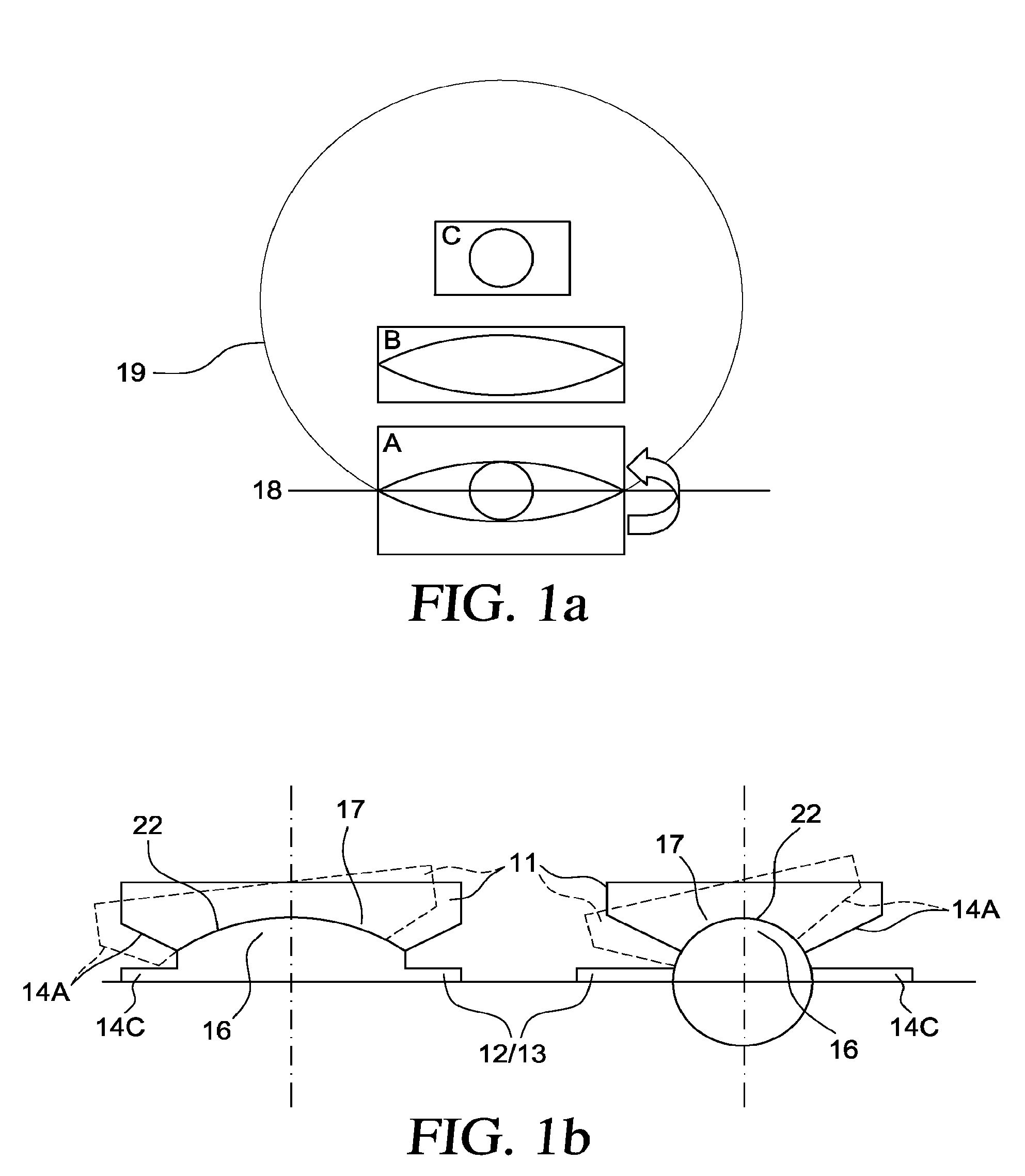
[0141]In FIG. 1a, part A of the figure shows how the curvation of the surfaces of a middle sliding partner with identical upper and lower sides are derived from a circumference 19 and originates from the rotation of the smaller segment of a circle, which is indicated by the arrow, around the secant 18. Part B of the figure shows the shape resulting from the rotation, which is identical in a frontal and transversal section. In a sagittal section C of the solid body, which originates from the rotation of the smaller segment of a circle around the secant 18, it has in each view a circular cross-section. The radii within the sagittal section decrease continuously from the middle of the geometric body to both lateral sides.

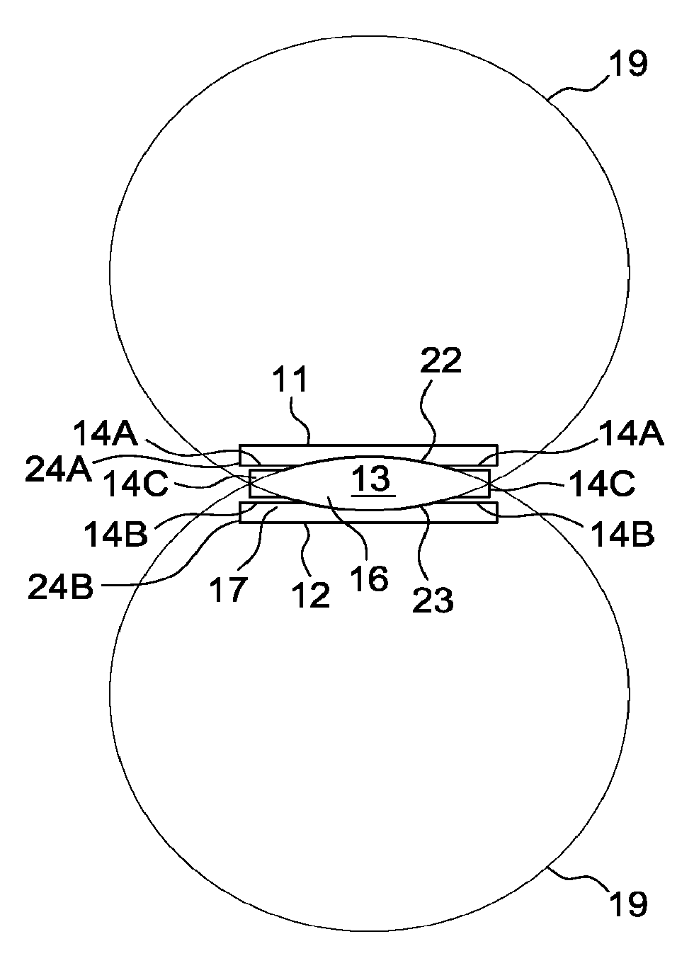
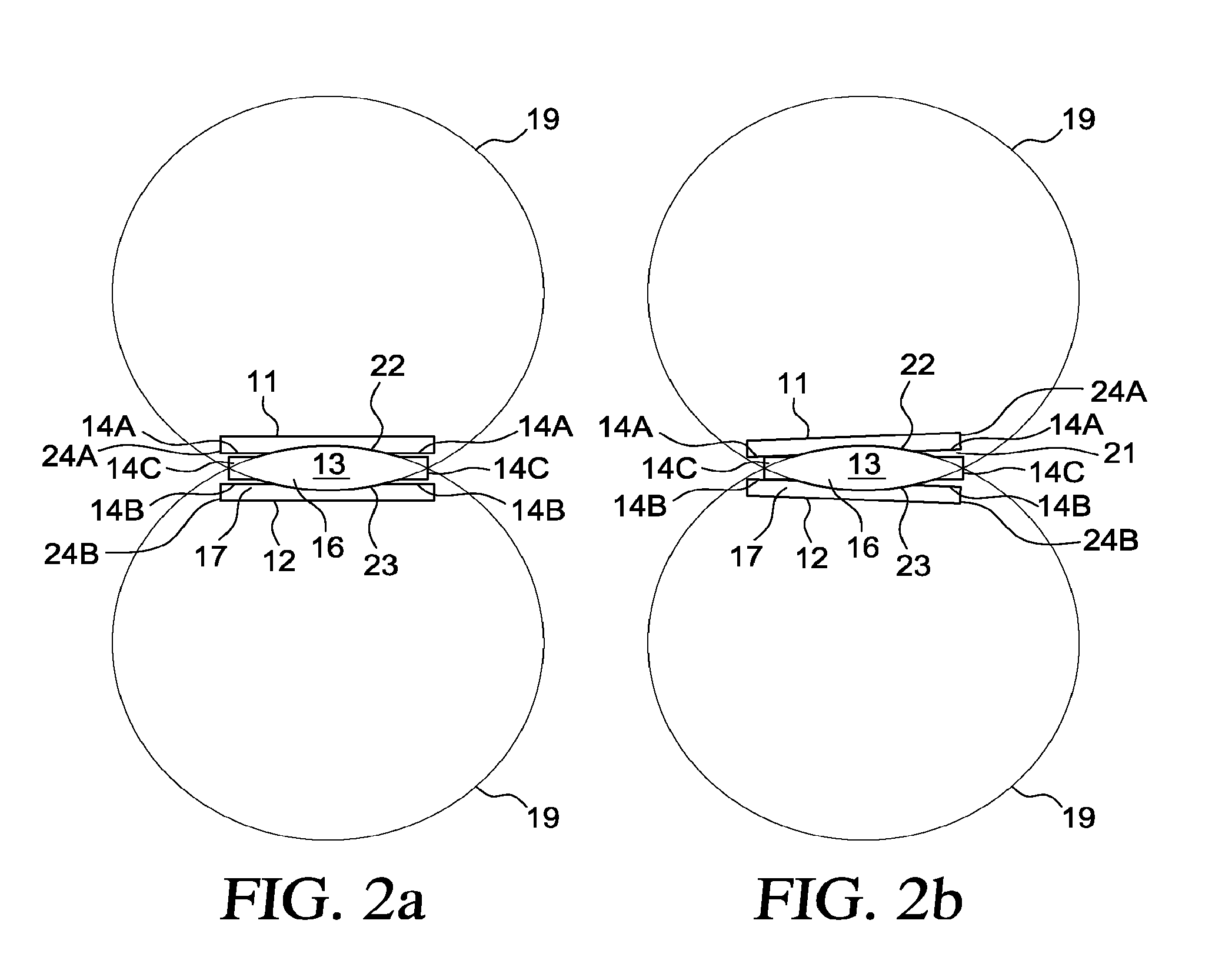
[0142]In FIG. 1b, the left schematically depicts a frontal view of a sliding area 22, 23 of an intervertebral two-part or three-part disc prosthesis, as per the invention. The right part of FIG. 1b schematically shows a sagittal view. The figure illustrates the identic...


PUM


Abstract

Disclosed is an intervertebral disc prosthesis for the total replacement of a natural intervertebral disc within the lumbar and cervical spine, comprising of articulating sliding partners. The upper sliding partner has means for a firm assembly to an upper vertebral body and the lower sliding partner has means for a firm assembly to a lower vertebral body. At least one sliding surface is between two sliding partners. Two- and three-part functional designs are planned and both having in common, that, as a result of the shape of the articulating surface(s), the laterolateral and dorsoventral motion amplitudes differ. The resulting angles including the rotation around a fictitious vertical axis can be defined to a desired extent.

Description

CROSS REFERENCE SECTION[0001]This is a divisional application of U.S. application Ser. No. 11 / 379,080, filed Apr. 18, 2006 which is a continuation-in-part application of international application no. PCT / DE2005 / 001884, filed Oct. 18, 2005 designating the U.S. and claiming priority from international application no. PCT / DE2004 / 002331, filed Oct. 18, 2004. These applications are incorporated herein by reference in their entirety.FIELD OF THE INVENTION[0002]The invention relates to an intervertebral disc prosthesis for the total replacement of an intervertebral disc of the lumbar and cervical spine.BACKGROUND OF THE INVENTION[0003]The idea of function-retaining artificial replacements for intervertebral discs is younger than that for replacements of artificial joints of extremities, but nonetheless about 50 years old [Büttner-Janz, Hochschuler, McAfee (Eds.): The Artificial Disc. Springer Verlag, Berlin, Heidelberg, New York 2003]. It is a response to biomechanical considerations, unsa...

Claims


Application Information

Patent Timeline
Patent Type & Authority Applications(United States)
IPC IPC(8): A61F2/44
CPCA61F2/4425A61F2310/00269A61F2002/3008A61F2002/30285A61F2002/30286A61F2002/30327A61F2002/30365A61F2002/30383A61F2002/30433A61F2002/30448A61F2002/305A61F2002/30662A61F2002/30795A61F2002/30841A61F2002/30904A61F2002/443A61F2220/0025A61F2220/0033A61F2220/0041A61F2220/005A61F2230/0063A61F2230/0071A61F2250/0039A61F2250/0098A61F2310/00023A61F2310/00029A61F2310/00131A61F2/4611
Inventor BUTTNER-JANZ, KARINBUTTNER, EIKO
Owner BUETTNER JANZ KARIN
Why Eureka
Try Eureka