
Crowning profile

Inactive Publication Date: 2010-06-03
VOLVO LASTVAGNAR AB
View PDF2 Cites 6 Cited by
  • Summary
  • Abstract
  • Description
  • Claims
  • Application Information

AI Technical Summary

Benefits of technology

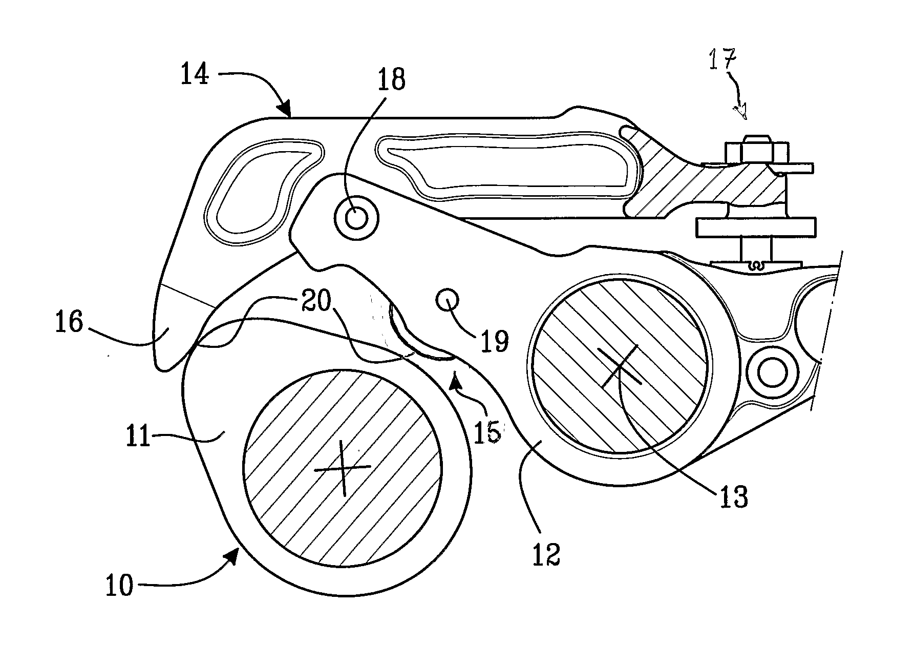
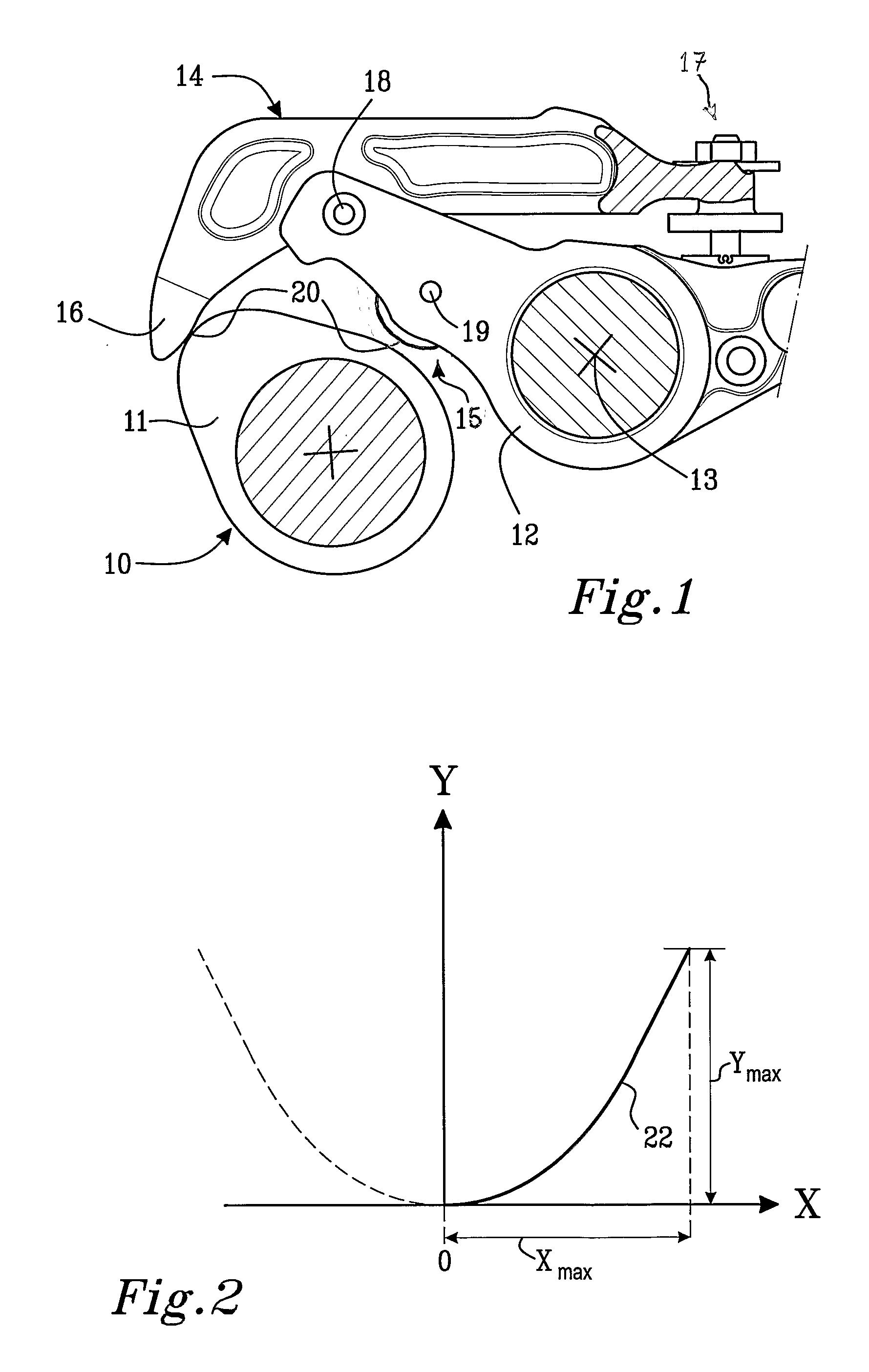
[0002]Contact elements that are arranged to be rotatably or pivotably mounted and to abut against mating parts so as to come into rolling or sliding contact with the mating parts are sometimes provided with a crowned contact surface. The crowned contact surface distributes pressure uniformly over the contact surface and prevents excessively high contact pressure from being generated at the ends of a contact surface. Increased contact pressure on a contact surface accelerates the wear, scuffing and exfoliation of the contact surface. This can result in unstable rotation and skidding of a contact element across its mating part, which consequently decreases the working lifetime of both the contact element and the mating part and adversely affects the performance and reliability of any system containing said components.
[0003]Crowning also compensates for minor misalignment of a contact element with its mating part thereby suppressing increases in contact pressure resulting from non-parallel contact. However, if said misalignment is too large, due to manufacturing and / or assembling imperfections, the advantages of using a crowned contact surface are reduced or eliminated.
[0005]It is desirable to provide a contact element that is arranged to follow, i.e. slide or roll, against a mating part and that comprises a contact surface having a crowning profile on at least a part thereof, i.e. at least part, if not the whole of the contact surface has a crowning profile, which helps to extend the working lifetime of the contact element and the mating part.
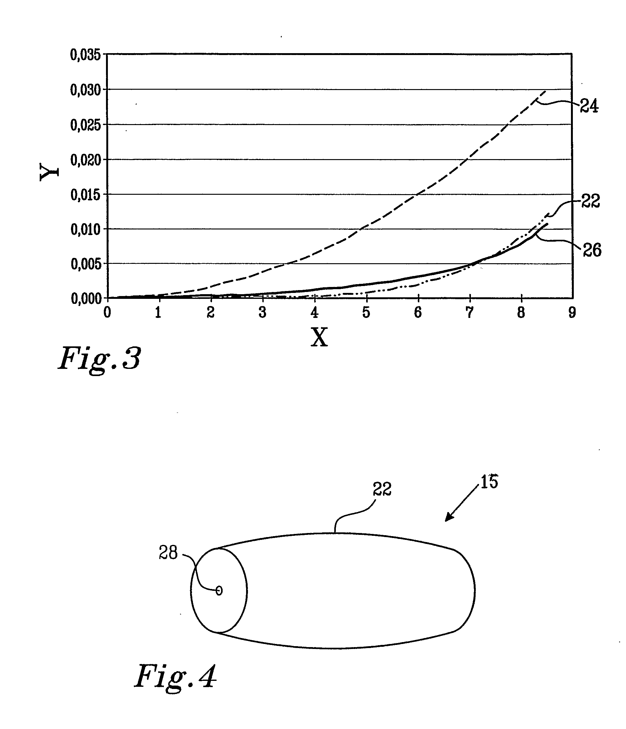
[0007]The inventive crowning profile enlarges the contact area between the contact element and the mating part compared to a spherical or a logarithmic crowning profile, which means that a contact element comprising such a crowning profile can withstand greater contact forces. The inventive crowning profile also helps to maintain a more uniform contact pressure distribution over the contact surface of the contact element, it reduces the wear of the contact element and thus increases the working lifetime of both the contact element and its mating part, which results in systems with improved reliability.
[0016]Once an optimum crowning profile for a particular application has been determined a contact element having that optimum crowning profile may be manufactured. The contact element is thereby provided with a smooth contact surface that compensates for any amount of misalignment or a predetermined allowable amount of misalignment of the contact element and its mating part. The inventive crowning profile consequently prevents excessive edge loading that occurs due to such misalignment since it has been adapted to a given geometry taking either all, or most of the possible inclined positions of the contact element and mating part into account. The custom-made crowning profile is therefore insensitive or less sensitive to manufacturing and / or assembling tolerances depending on whether Ymax′ is set equal to the maximum or probable range of variation in maintaining specified dimensions on manufacturing and / or assembling a contact element and / or its mating part. In other words even if the contact element having the inventive profile becomes misaligned with its mating part prior to or during its use due to manufacturing and / or assembling imperfections, increases in the contact pressure will be suppressed and damage to the contact surfaces of the contact element and mating part will be prevented, thus maintaining the performance of a system, such as an internal combustion engine, comprising said contact element and mating part.

Problems solved by technology

Increased contact pressure on a contact surface accelerates the wear, scuffing and exfoliation of the contact surface.
This can result in unstable rotation and skidding of a contact element across its mating part, which consequently decreases the working lifetime of both the contact element and the mating part and adversely affects the performance and reliability of any system containing said components.
Contact elements comprising a spherical crowning profile contact a mating part at a point, which greatly reduces friction between said components but if such a contact element is overloaded, i.e. if the contact pressure at the contact point is too high, the contact element can deform and be ruined.
Contact elements having a logarithmic crowning profile are however difficult to fabricate.
Hertz's theory can not be used to calculate an accurate contact pressure and area for contact elements having the Inventive crowning profile because such contact elements do not have a constant radius of curvature.

Method used


Image

  • Crowning profile
  • Crowning profile
  • Crowning profile

Examples


example

[0029]In order to calculate the optimum crowning profile 22 for a contact element 16 having a contact surface of width 2Xmax a plurality of values B from 2-20 is chosen. The maximum allowed range of variation permitted in maintaining specified dimensions on manufacturing and / or assembling a contact element, Ymax′ is determined and the following formula is used to determine an A value corresponding to each B value.

Ymax′=ABXmaxB-1

[0030]Crowning profiles for each set of A and B values can then be defined using the function:

Y=AXB

[0031]The total or maximum contact pressure generated on contact surfaces having such crowning profiles is then approximated using Hertz's theory or calculated using finite element analysis.

[0032]The crowning profile resulting in the lowest total or maximum contact pressure being generated on the contact surface of a contact element that is intended for a particular application is then chosen as the optimum crowning profile for that contact element.


PUM


Abstract

A contact element that is arranged to follow, i.e. slide or roll, against a mating part includes a contact surface having a crowning profile on at least a part thereof. The crowning profile is defined by the function Y(X)=AX6 where Y is the crowning quantity, X is the distance from the centre of the contact surface of the contact element, A and B are real numbers and B is greater than 2.

Description

BACKGROUND AND SUMMARY[0001]The present invention concerns a contact element that is arranged to be rotatably mounted and to abut against a mating part, said contact element comprising an at least partly crowned contact surface. “Rotatably mounted” is intended to mean than the contact element is able turn through at least part of one revolution about an axis and thus includes contact elements that are pivotably mounted.[0002]Contact elements that are arranged to be rotatably or pivotably mounted and to abut against mating parts so as to come into rolling or sliding contact with the mating parts are sometimes provided with a crowned contact surface. The crowned contact surface distributes pressure uniformly over the contact surface and prevents excessively high contact pressure from being generated at the ends of a contact surface. Increased contact pressure on a contact surface accelerates the wear, scuffing and exfoliation of the contact surface. This can result in unstable rotatio...

Claims


Application Information

Patent Timeline
IPC IPC(8): G06F17/50F16H53/00G06F17/10
CPCF01L1/16F01L1/181F01L1/20F01L1/26Y10T74/2101F01L2001/186F01L2103/00F01L2105/00F01L2820/02F01L13/06F01L2303/00F01L2305/00
Inventor GUSTAFSSON, MAGNUS
Owner VOLVO LASTVAGNAR AB
Learn More