Coaxial cable and manufacturing method of the same

a manufacturing method and coaxial cable technology, applied in the direction of power cables, cables, insulated conductors, etc., can solve the problems of external deformation, difficult to manufacture a long coaxial cable, and further micronizing the cabl

Inactive Publication Date: 2010-06-10
HITACHI METALS LTD
View PDF9 Cites 20 Cited by
  • Summary
  • Abstract
  • Description
  • Claims
  • Application Information

AI Technical Summary

Benefits of technology

[0029]According to the present invention, the micro-coaxial cable having a resistance to deformation, can be obtained.

Problems solved by technology

Meanwhile, in a method of forming the conductive layer by winding the metal wires or the metal film around the outer periphery of the insulating layer, it is difficult to manufacture a long coaxial cable, with a tendency of further micronizing a cable (for example, see patent document 1).
However, there is a problem of easily causing external deformation such as bending to occur, when a force is added to a micro-cable which is formed by decreasing a wire diameter of the cable.
Even in a case of a slight external deformation such as bending that occurs in the micro-cable, there is a problem that decline of adhesion occurs between an insulating layer in the cable and a shield layer made of a metal thin film.
By such a low adhesion between the insulating layer and the metal thin film, there is also a problem that the metal thin film is peeled off from the insulating layer, thus causing a breakage of the metal thin film.
As a result, conductivity of the shield layer, being a conductive layer, becomes insufficient, and shield characteristics are deteriorated.
However, this method involves a problem that a working process is complicated, a facility cost is increased, and a waste liquid is generated, thus posing a problem in terms of mass-production.
When the insulating layer is also heated, there is a possibility that decline of adhesion occurs between the insulating layer and the metal thin film, due to deformation and change of quality of the insulating layer.
Therefore, even in a case of a slight external deformation such as bending that occurs in the micro-cable, there is a possibility that the metal thin film is peeled off from the insulating layer, thus causing the breakage of the metal thin film.
As a result, there is a possibility that conductivity of the shield layer, being the conductive layer, becomes insufficient, and the shield characteristics are deteriorated.

Method used


Image

  • Coaxial cable and manufacturing method of the same
  • Coaxial cable and manufacturing method of the same
  • Coaxial cable and manufacturing method of the same

Examples


first embodiment

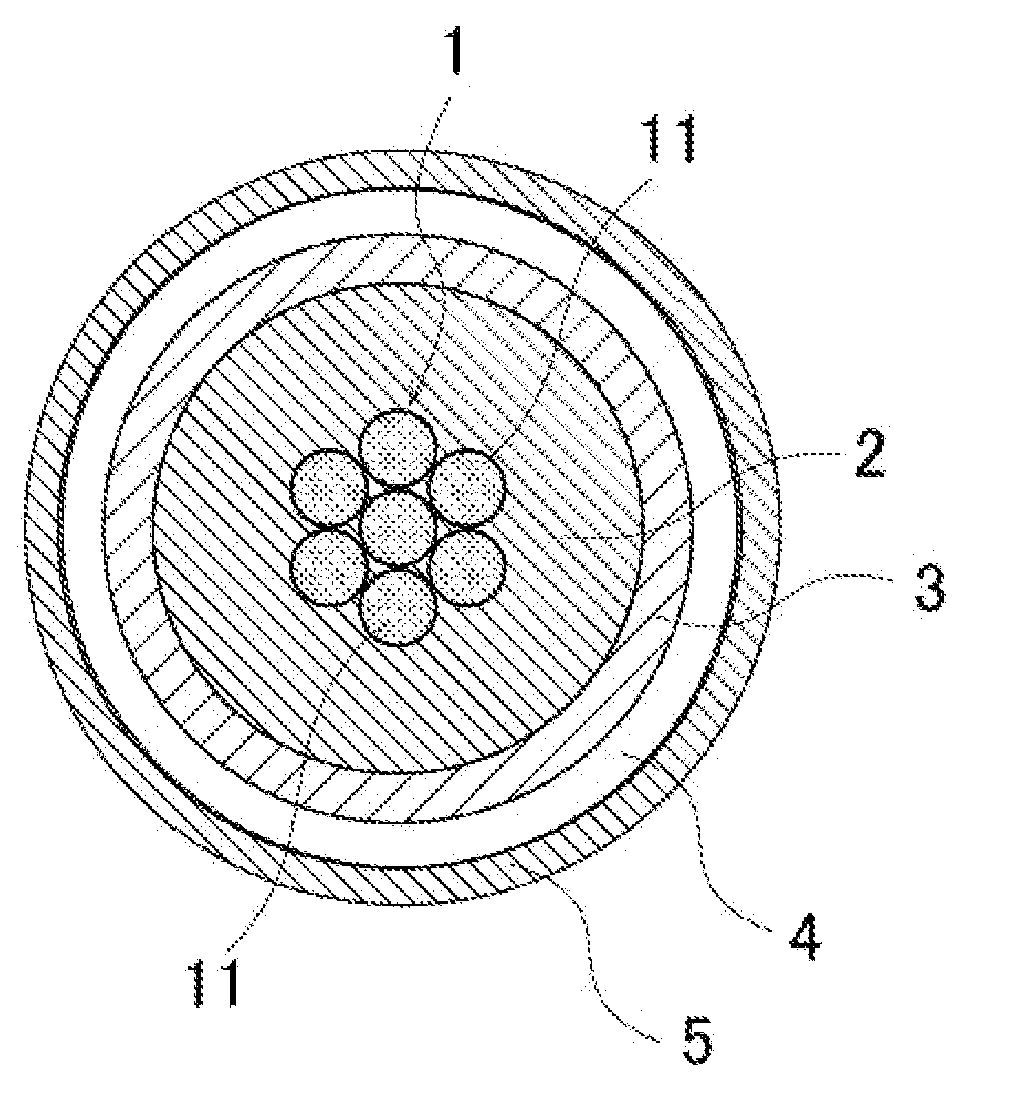
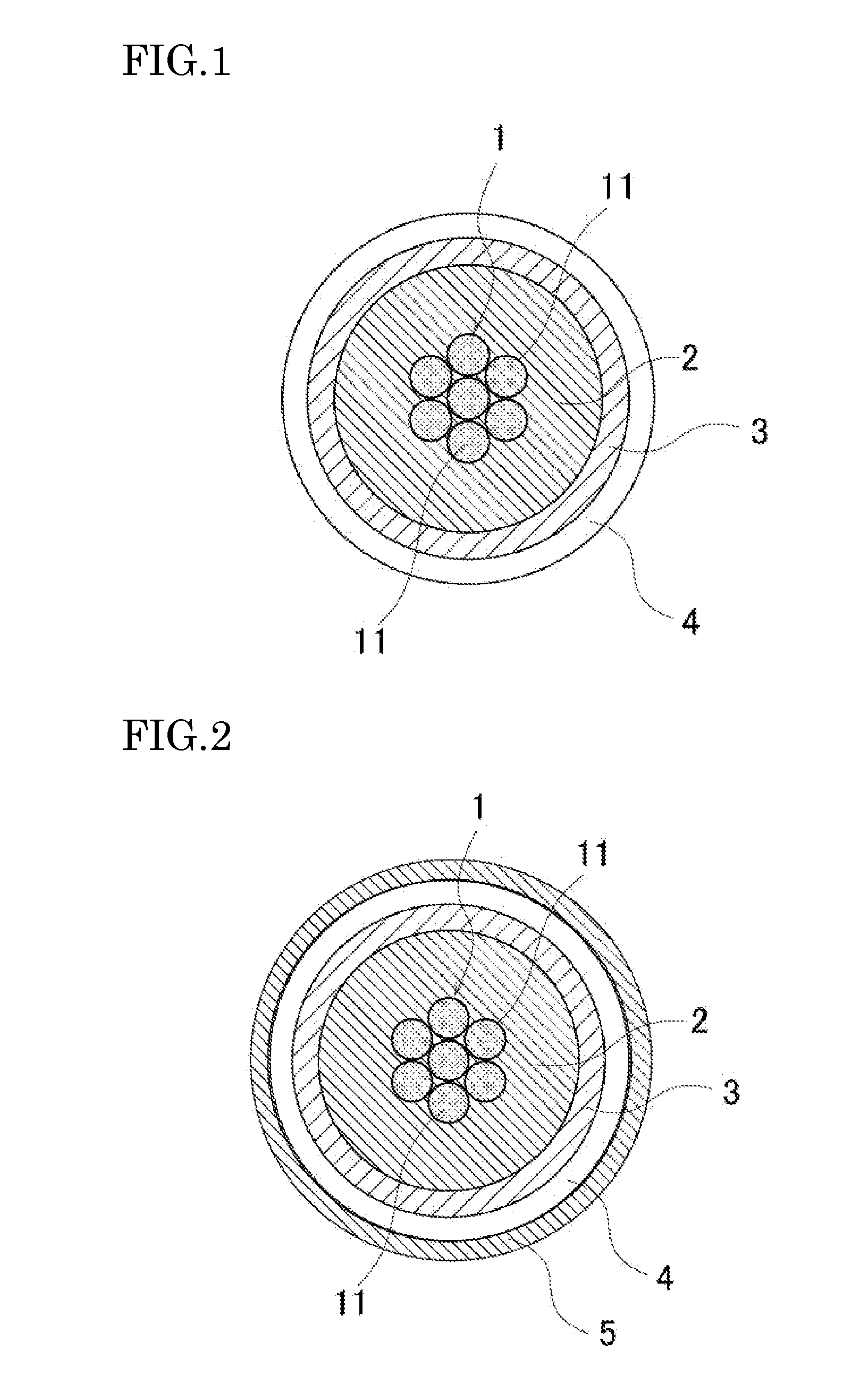
[0035]FIG. 1 shows a sectional structure of an embodiment of a coaxial cable of the present invention. As shown in FIG. 1, in the coaxial cable, an internal insulating layer 2 is formed on an outer periphery of an electric conductor 1, and a conductive layer 3 is formed on an outer periphery of the internal insulating layer 2, and further an external insulating layer 4 is formed on an outer periphery of the conductive layer 3.

[0036]First, the electric conductor 1 is composed of long central twisted conductors 11 with cross-sectional face formed into round shapes (also called core wires 11 hereinafter). Metal is used in the central conductors 11, and for example a copper alloy is used. The central conductors 11 may be made of, for example, a single copper wire or a plurality of twisted wires or braided wires, and hot dip plating or tin plating by electrolytic conversion treatment may be applied to the copper wire.

[0037]Although as an insulating layer, resin of a low dielectric consta...

second embodiment

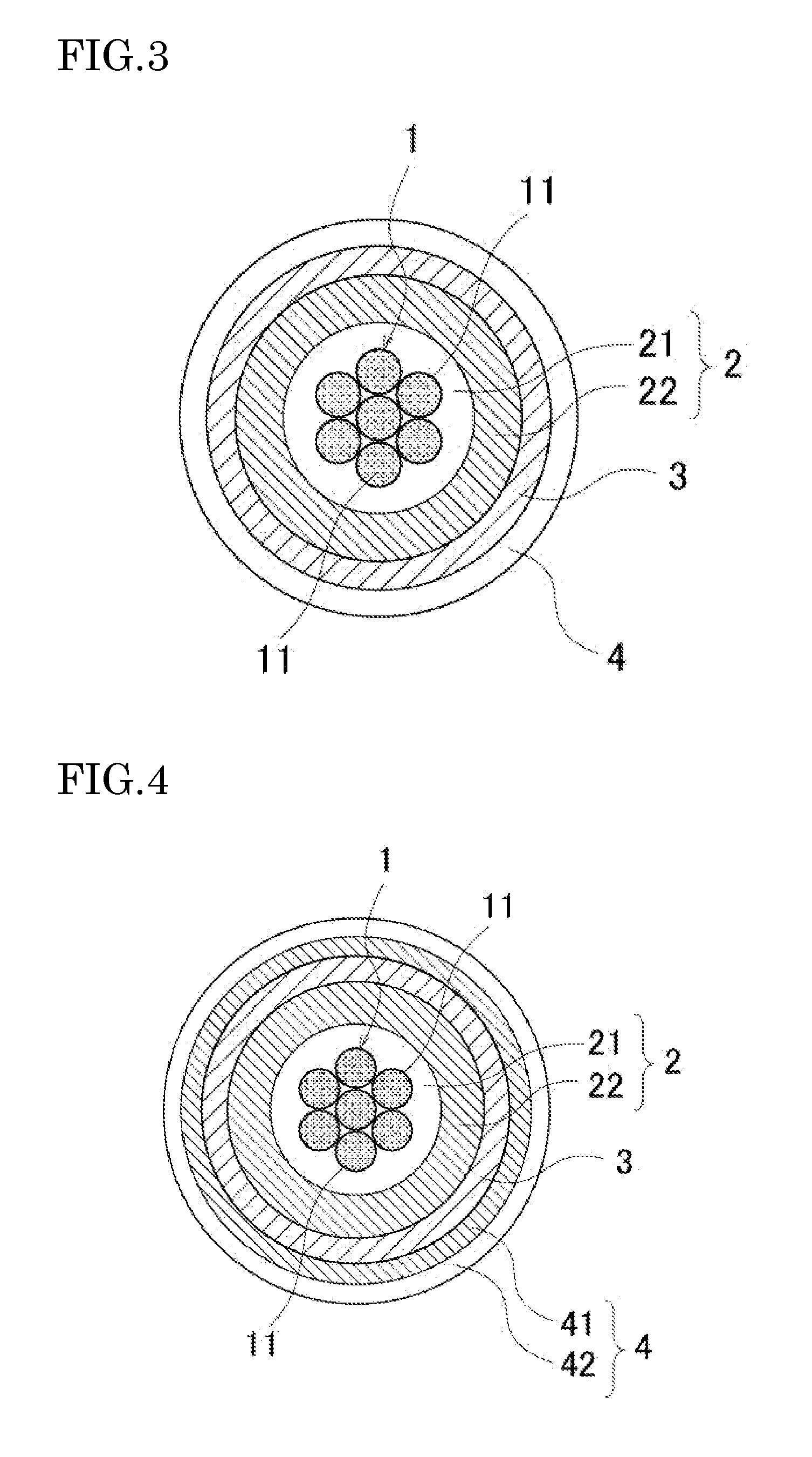
[0069]FIG. 3 shows a cross-sectional structure of another embodiment of the coaxial cable. A different point from the first embodiment is that the internal insulating layer 2 formed on the outer periphery of the electric conductor 1 has a two-layer structure. Namely, in the internal insulating layer 2 formed on the outer periphery of the electric conductor 1, PFA having low adhesion compared with adhesion of the grafted PFA is used in an inner layer (also called a first internal insulating layer 21 hereinafter), and a grafted PFA having relatively high adhesion is used in an outer layer (also called a second internal insulating layer 22 hereinafter) formed on the outer periphery of the inner layer.

[0070]By manufacturing such a coaxial cable, the coaxial cable capable of responding to the following case can be obtained. Namely, when the adhesion between the internal insulating layer 2 and the conductive layer 3 is desired, although the adhesion between the core wires 11 of the electr...

third embodiment

[0071]FIG. 4 shows a cross-sectional structure of another embodiment of the coaxial cable of the present invention.

[0072]Different points from the first embodiment are that the internal insulating layer 2 formed on the outer periphery of the electric conductor 1 has a two-layer structure, and the external insulating layer 4 formed on the outer periphery of the conductive layer 3 has a two-layer structure. Namely, in the external insulating layer 4 formed on the outer periphery of the conductive layer 3, the grafted PFA having relatively high adhesion is used in an inner layer (also called a first external insulating layer 41 hereinafter), and the PFA having lower adhesion than the adhesion of the grafted PFA is used in an outer layer (also called a second external insulating layer 42).

[0073]By manufacturing the aforementioned coaxial cable, the following effect can be obtained.

[0074]Namely, by sandwiching the conductive layer 3, being the metal nanoparticle paste sintered body, betw...


PUM

PropertyMeasurementUnit
sizeaaaaaaaaaa
particle sizeaaaaaaaaaa
wavelengthaaaaaaaaaa

Abstract

A coaxial cable includes an internal insulating layer formed on an outer periphery of an electric conductor, and a conductive layer formed on an outer periphery of the internal insulating layer, wherein the conductive layer is made of a metal nanoparticle paste sintered body obtained by sintering metal nanopraticles by irradiation of light toward a metal nanoparticle paste, and an external insulating layer is formed on an outer periphery of the conductive layer.

Description

BACKGROUND[0001]1. Technical Field[0002]The present invention relates to a coaxial cable and a manufacturing method of the same, and particularly relates to a micro-coaxial cable using a metal nanoparticle paste sintered body in a conductive layer, and the manufacturing method of the same.[0003]2. Description of Related Art[0004]In a general coaxial cable, a low permeability insulating layer is formed on an outer periphery of an electric conductor positioned in a center. Further, a conductive layer is formed on an outer periphery of the insulating layer, by winding metal wires or a metal film around the outer periphery of the insulating layer. The conductive layer serves as a shield layer.[0005]Meanwhile, in a method of forming the conductive layer by winding the metal wires or the metal film around the outer periphery of the insulating layer, it is difficult to manufacture a long coaxial cable, with a tendency of further micronizing a cable (for example, see patent document 1).[000...

Claims


Application Information

Patent Timeline
Patent Type & Authority Applications(United States)
IPC IPC(8): H01B11/18B05D3/06
CPCB05D2256/00H01B11/1817H01B3/445H01B13/24B82Y30/00H01B13/225
Inventor ABE, TOMIYAISHIKAWA, DAIITO, MASANOBUTSUCHIYA, TADAYOSHI
Owner HITACHI METALS LTD
Why Eureka
Try Eureka