High temperature seal assembly for optical sensor

a technology of sealing assembly and optical sensor, which is applied in the direction of optical radiation measurement, lighting and heating apparatus, instruments, etc., can solve the problems of not able to withstand the operating temperature present in close proximity to the combustion flame, to the metal seal, and the conventional kovar-to-sapphire braze seal

Active Publication Date: 2010-06-10
ROSEMOUNT AEROSPACE
View PDF27 Cites 30 Cited by
  • Summary
  • Abstract
  • Description
  • Claims
  • Application Information

AI Technical Summary

Benefits of technology

[0012]In a preferred embodiment of the subject invention, the high temperature seal assembly is associated with a fuel injector for a gas turbine engine. Accordingly, the subject invention is directed to a fuel injector that includes a nozzle body having a leading edge surface with an optical viewing por

Problems solved by technology

However, it has been determined that a ceramic-to-metal seal is very sensitive to thermal expansion, and thus not suitable for applications in which the optical sensor is located in close proximity to a combustion flame, where temperatures can reach as high as 1400° F.
While a seal between a Kovar lens holder and a sapphire

Method used


Image

  • High temperature seal assembly for optical sensor
  • High temperature seal assembly for optical sensor
  • High temperature seal assembly for optical sensor

Examples


Embodiment Construction

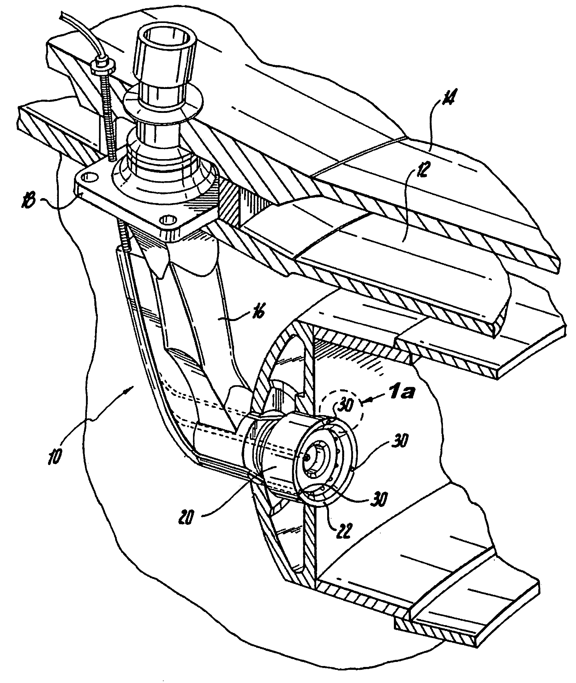
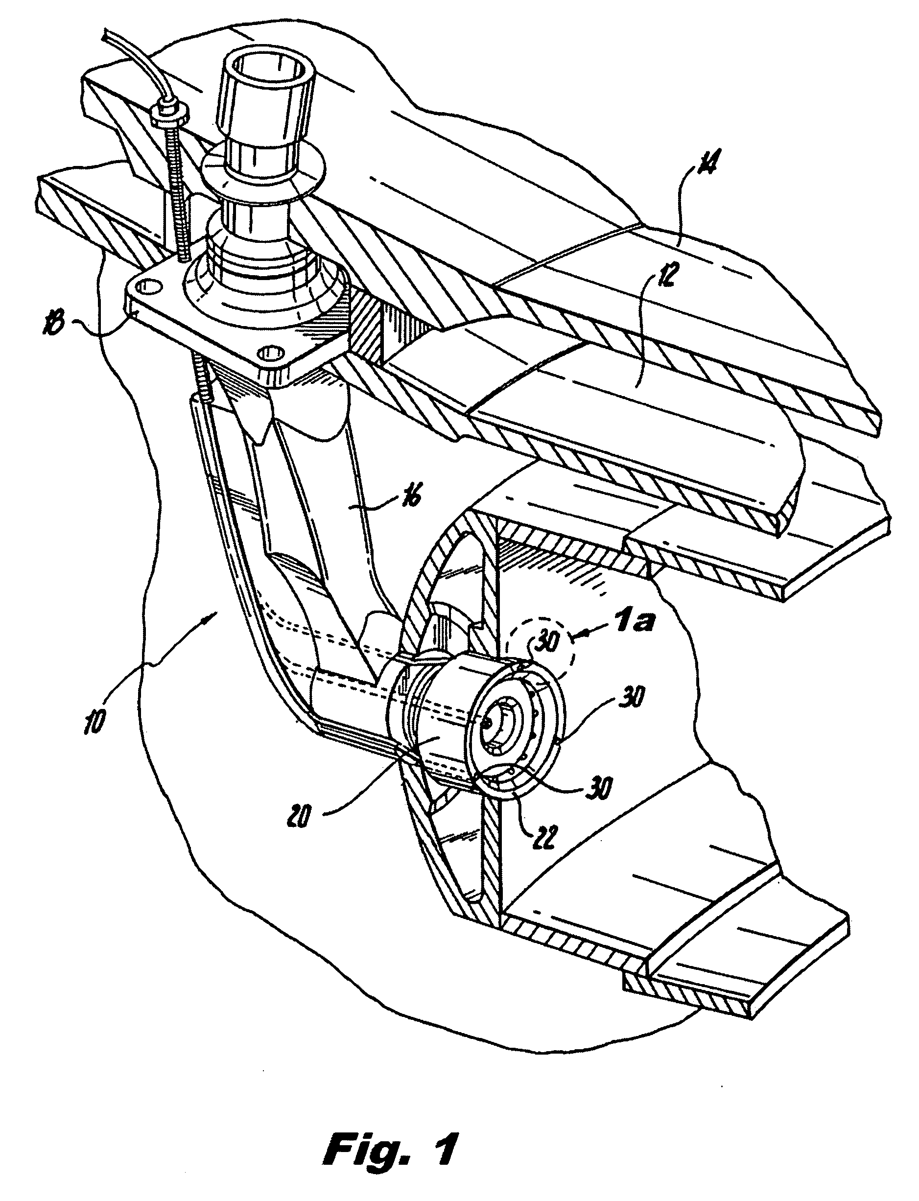
[0021]Referring now to the drawings wherein like reference numerals identify similar structural features or elements of the subject invention, there is illustrated in FIG. 1 an instrumented fuel injector configured in accordance with a preferred embodiment of the subject invention and designated generally by reference numeral 10.

[0022]Fuel injector 10 is of type disclosed in commonly assigned U.S. Pat. No. 7,334,413 to Myhre, the disclosure of which is herein incorporated by reference in its entirety. In brief, fuel injector 10 is mounted or otherwise supported within the combustion chamber 12 of gas turbine engine 14 in a conventional manner. Fuel injector 10 includes an elongated feed arm 16 having a support flange 18 for mounting the injector within the combustion chamber 12. A fuel nozzle 20 depends from the distal end of feed arm 16 and is designed to inject or otherwise issue atomized fuel into the combustion chamber 12.

[0023]In accordance with a preferred embodiment of the su...


PUM


Abstract

A seal assembly for an optical sensor employed in a high temperature environment is disclosed which includes an elongated metal guide tube having a distal end portion defining an open distal end and an inner rear wall, a sapphire window disposed within the distal end portion of the metal guide tube, the sapphire window having a rear end surface abutting the inner rear wall of the distal end portion of the metal guide tube, and a platinum mounting sleeve for securing the sapphire window to the metal guide tube, the platinum mounting sleeve having one portion joined to the metal guide tube and another portion joined to the sapphire window.

Description

GOVERNMENT RIGHTS STATEMENT[0001]The U.S. Government has a paid-up license in this invention and the right in limited circumstances to require the patent owner to license others on reasonable terms as provided for by the terms of FA8650-07-C-2796, awarded by the Air Force Research Laboratory.BACKGROUND OF THE INVENTION[0002]1. Field of the Invention[0003]The subject invention is directed to a seal assembly for an optical sensor employed in a high temperature environment, and more particularly, to a seal assembly for an optical sensor employed in a fuel injector of a gas turbine engine.[0004]2. Description of Related Art[0005]Over the past decade, there has been increased use of optical probes to monitor industrial processes taking place in harsh environments. Examples include optical pyrometers for measuring temperature and fiber optic spectrometers for measuring chemical compositions. To protect and otherwise extend the operational life of these optical probes, they are often house...

Claims


Application Information

Patent Timeline
IPC IPC(8): B05B15/06H01J5/02F16J15/00
CPCF23M11/045F23N5/082F23N2900/05005F23R3/002F23R3/28G01J5/048G01J5/00G01J5/0088G01J5/04G01J5/042F23R2900/00012F02C9/00F23N5/08G01J5/045G01J5/046
Inventor MYHRE, DOUGLAS C.MICHEL, JOSEPH R.
Owner ROSEMOUNT AEROSPACE
Why Eureka
Try Eureka