Wind turbine and method of assembling the same

Inactive Publication Date: 2010-06-10
GENERAL ELECTRIC CO
View PDF10 Cites 17 Cited by
  • Summary
  • Abstract
  • Description
  • Claims
  • Application Information

AI Technical Summary

Problems solved by technology

Further, such slew bearings require high precision fabrication and/or manufacturing, which may be time-consuming

Method used


Image

  • Wind turbine and method of assembling the same
  • Wind turbine and method of assembling the same
  • Wind turbine and method of assembling the same

Examples


Embodiment Construction

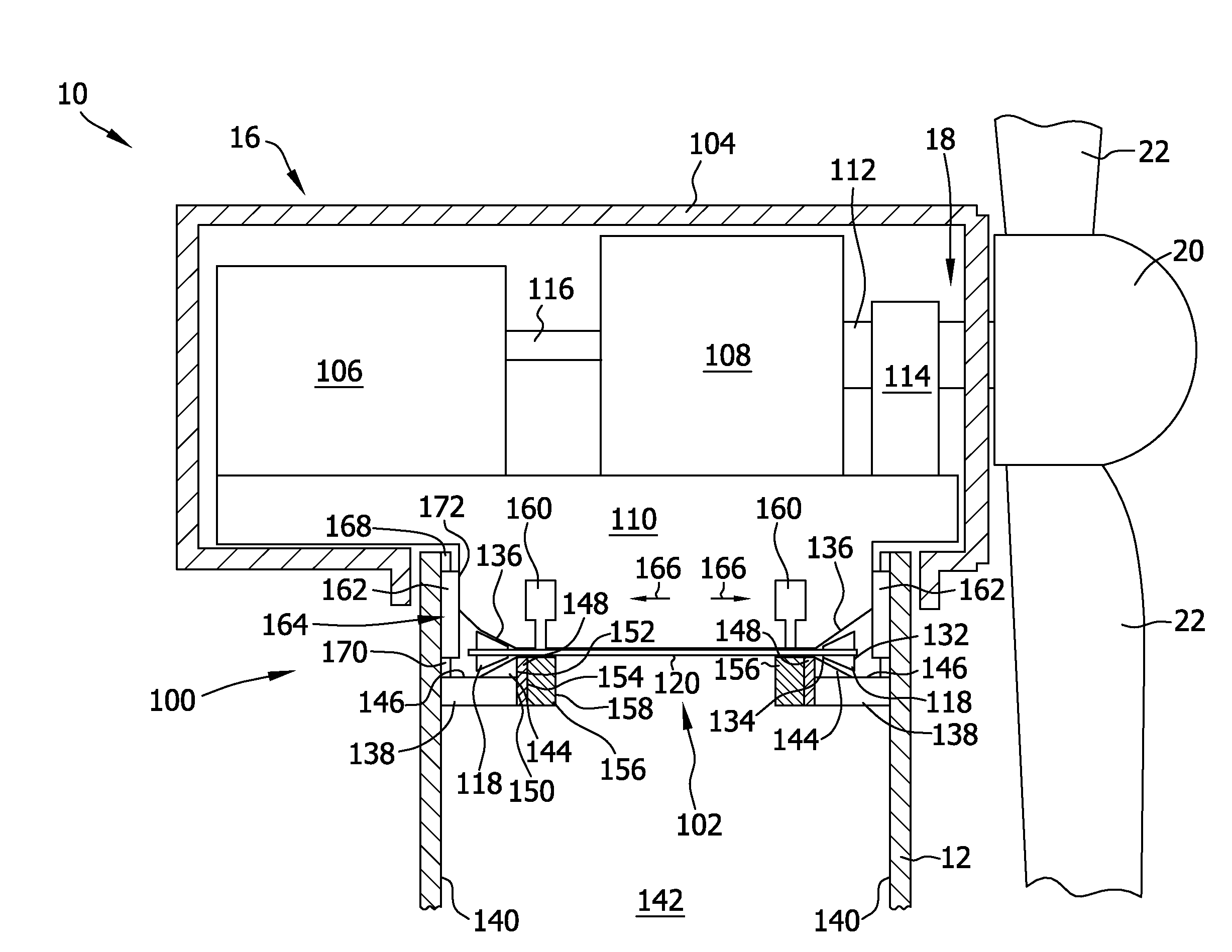
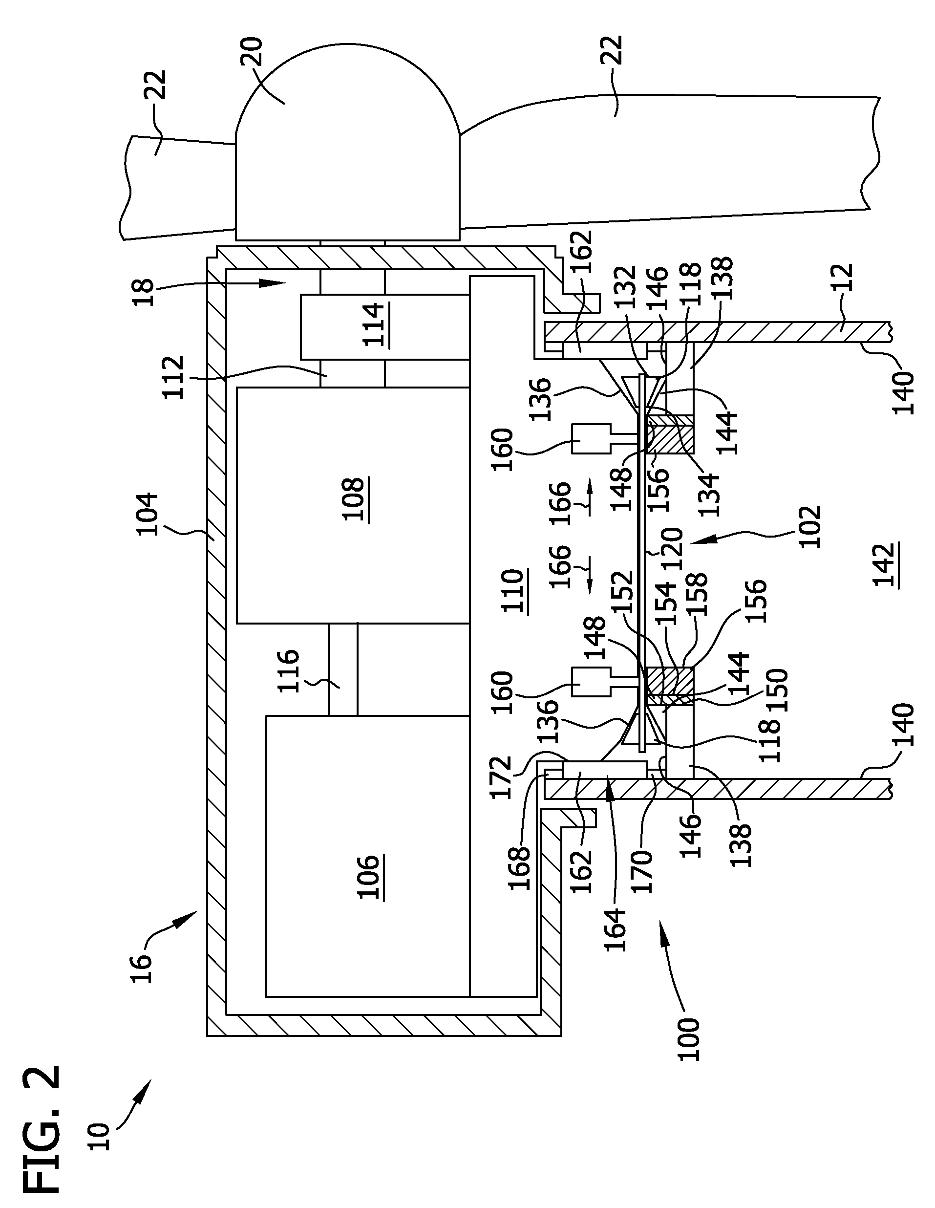
[0014]The embodiments described herein can be used with bucket-type yaw systems in which bending and / or torsion moments are supported laterally and a weight of the nacelle is supported by a flat or tapered bearing or a sliding ring, such as an open needle slew bearing. Such a bearing configuration does not require yaw breaks and / or high precision machining and / or fabrication of the bearing. Further, the embodiments described herein include at least one sliding pad that is in contact with a base of the nacelle and includes low friction material. Such a sliding pad supports the nacelle laterally while allowing the nacelle to rotate with respect to a tower.

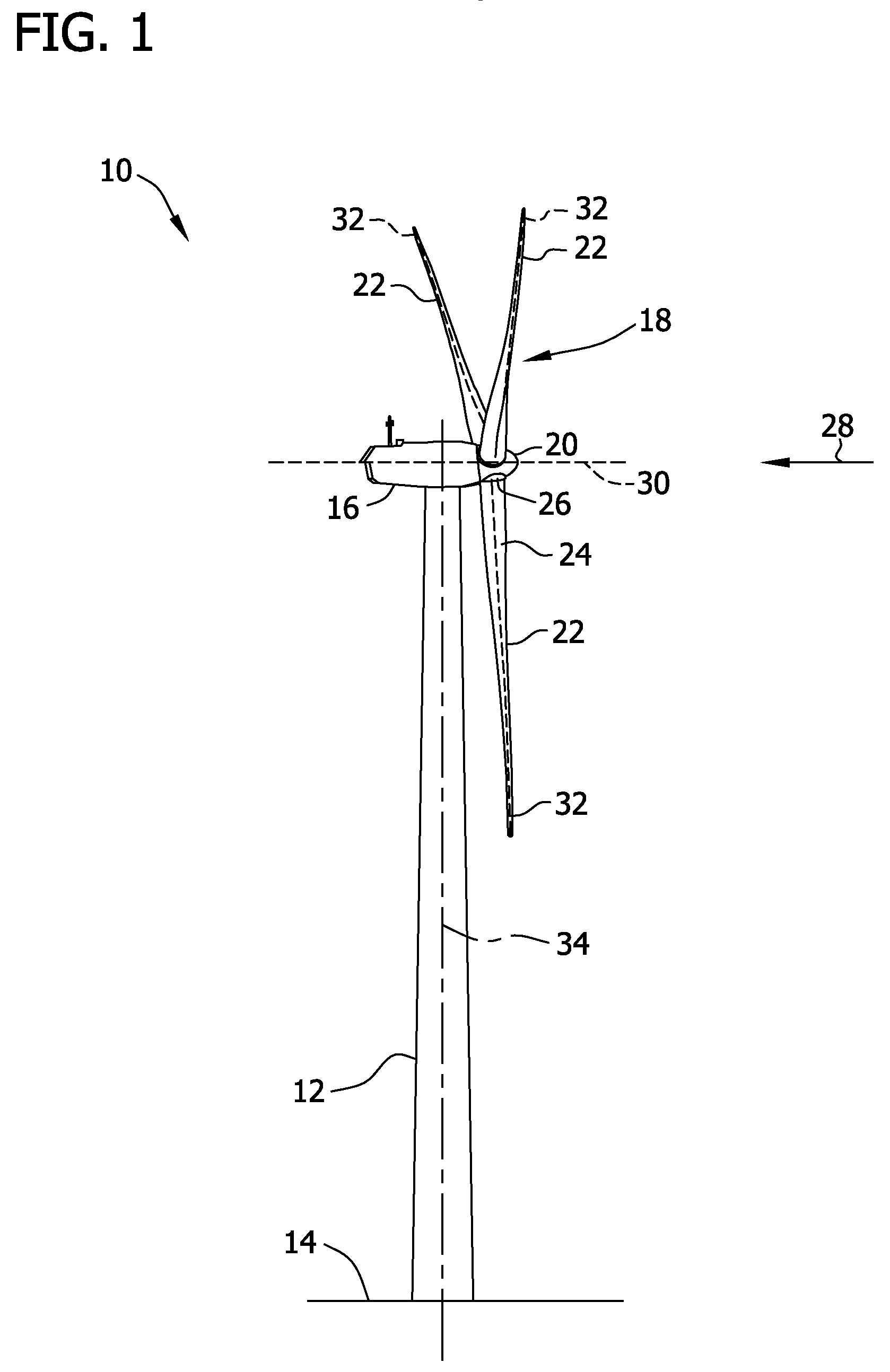
[0015]FIG. 1 is a side elevation view of an exemplary wind turbine 10. In the exemplary embodiment, wind turbine 10 is a nearly horizontal-axis wind turbine. In another embodiment, wind turbine 10 may have an up-tilt angle (not shown) ranging from about 1° to about 15°. Alternatively, wind turbine 10 may be a vertical axis wind turbi...


PUM

PropertyMeasurementUnit
Speedaaaaaaaaaa

Abstract

A method of assembling a wind turbine is provided. The method includes coupling a support flange to an inner surface of a tower, and positioning a yaw bearing on the support flange. The yaw bearing includes a plurality of horizontally oriented rollers. A base of a nacelle assembly is positioned on the yaw bearing such that the base is rotatable with respect to the tower.

Description

BACKGROUND OF THE INVENTION[0001]The embodiments described herein relate generally to nacelle assemblies for wind turbines and, more particularly, to a yaw bearing within a nacelle assembly.[0002]At least some known wind turbines include a yaw bearing between a nacelle and a tower of the wind turbine. The yaw bearing allows the nacelle to be rotated with respect to a direction of the wind. More specifically, the yaw bearing usually includes gearing and a yaw drive motor rotates by the nacelle by engaging the gearing of the yaw bearing.[0003]At least some known yaw bearings are slew bearings that include concentric races. Between the concentric races, the slew bearing can include balls, vertically oriented rollers, and / or a slide surface. The gearing can either be located on an inner surface of an inner race or an outer surface of an outer race. Either the inner race is coupled to the nacelle and the outer race is coupled to the tower, or the inner race is coupled to the tower and th...

Claims


Application Information

Patent Timeline
IPC IPC(8): F03D9/00
CPCF03D11/0008Y02E10/722Y10T29/49904Y10S415/908Y10S416/06F03D80/70F16C19/30F16C2360/31Y02E10/72
Inventor SEGOVIA, EUGENIO YEGROSANTIAGO, PEDRO LUIS BENITO
Owner GENERAL ELECTRIC CO
Why Eureka
Try Eureka