Switched Reluctance Machines with Minimum Stator Core

a technology of switching reluctance machines and stator cores, which is applied in the direction of dynamo-electric machines, electrical apparatus, magnetic circuit shapes/forms/construction, etc., can solve the problems of high cost of conventional two-phase srm drives, single-phase srm drives are not suitable for high-performance applications, etc., to achieve cost savings, shorten the path length of magnetic flux paths, and minimize the size of stator cores

Inactive Publication Date: 2010-06-10
VIRGINIA TECH INTPROP INC +1
View PDF12 Cites 22 Cited by
  • Summary
  • Abstract
  • Description
  • Claims
  • Application Information

AI Technical Summary

Benefits of technology

[0006]In accordance with the invention, a novel two-phase SRM (“TPSRM”) drive that minimizes the size of the stator core by using physically separate and discontinuous core structures is disclosed. Generally, the discontinuous core structures allow less stator core material and less magnet wire to be used in a TPSRM, which results in significant cost savings. Additionally, this generally shortens the path lengths of magnetic flux paths or loops during phase excitations and can be configured to operate with substantially no flux reversals in its stator core. As a result, the inventive TPSRM drive may reduce core losses and operate at a higher efficiency than prior TPSRM implementations.

Problems solved by technology

Induction motors and universal motors are being used in most applications requiring constant-speed and low-horsepower, mainly because of their competitive cost.
However, single-phase SRM drives are not suitable for high performance applications since they have some inherent limitations, including low output power density and only a 50% duty cycle of torque generation.
One drawback of conventional two-phase SRM drives is their cost.

Method used


Image

  • Switched Reluctance Machines with Minimum Stator Core
  • Switched Reluctance Machines with Minimum Stator Core
  • Switched Reluctance Machines with Minimum Stator Core

Examples


Embodiment Construction

[0034]Reference will now be made in detail to the present exemplary embodiments of the invention, examples of which are illustrated in the accompanying drawings. Wherever possible, the same reference numbers will be used throughout the drawings to refer to the same or like parts.

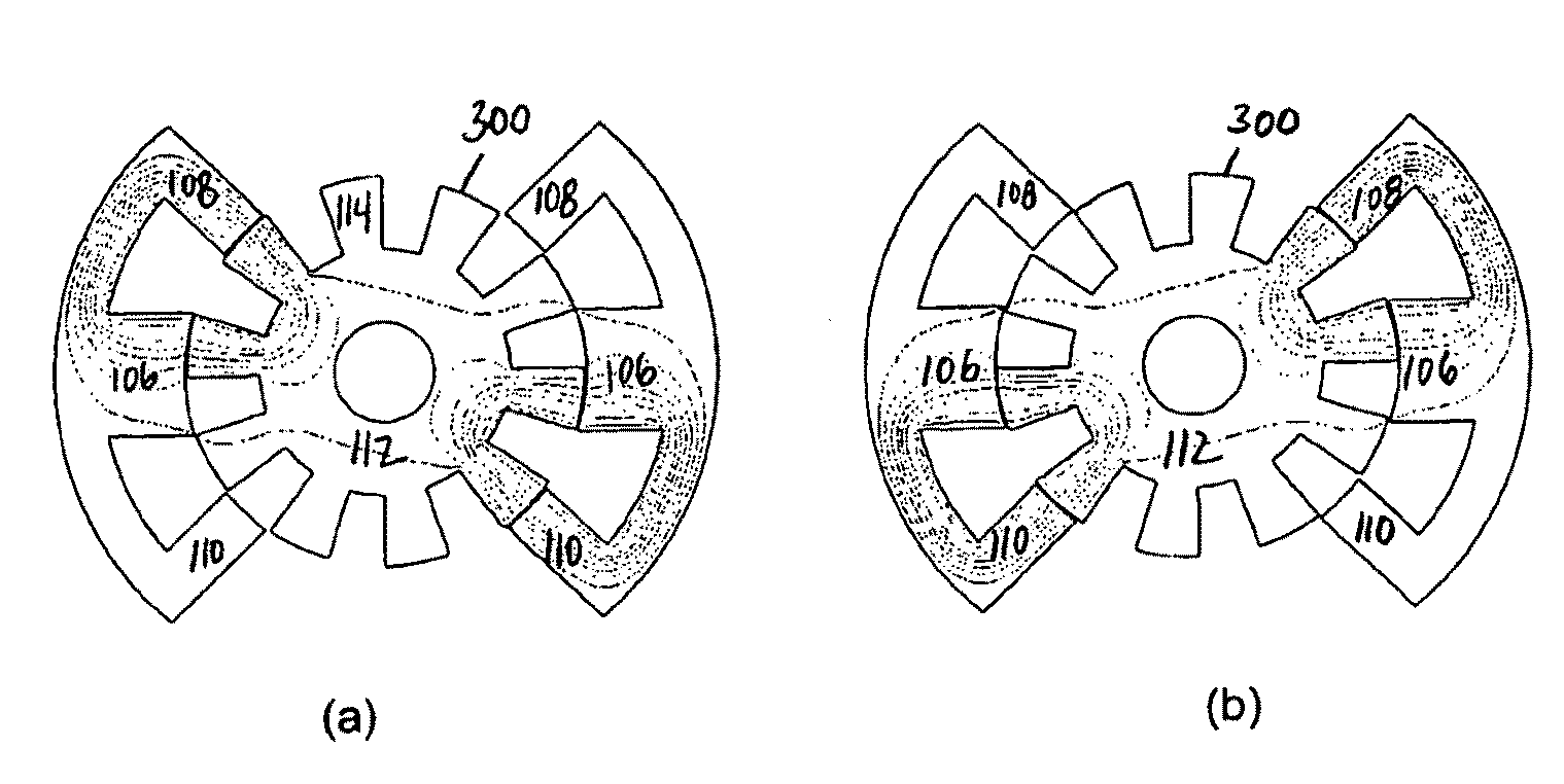
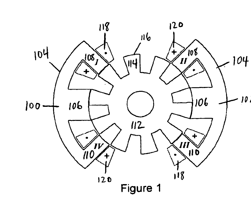
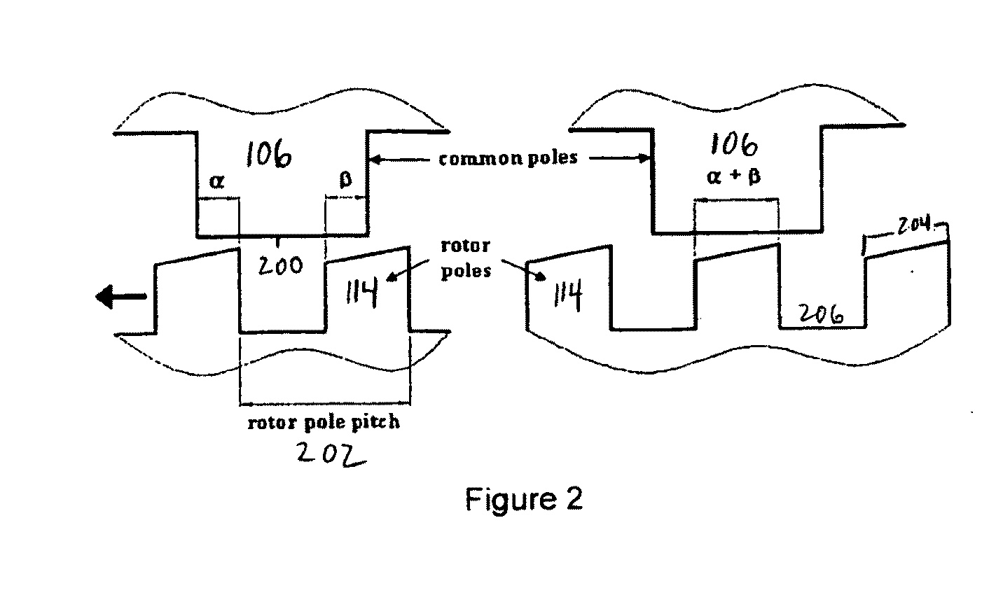
[0035]Examples of a novel two-phase SRM drive using physically separate and discontinuous core structures with minimum stator iron core are disclosed for high torque applications using short-pitch windings (i.e., concentric coil windings). Generally, the principles of such an SRM drive are explained below with reference to an exemplary “E-core” configured embodiment where the discontinuous stator core structures each have an arced main outer segment and are each shaped like an “E” with their respective poles. Other exemplary embodiments of the stator core structure use an angled main outer segment and are referred to as an “L-core” configuration while still other embodiments use a substantially straight main...


PUM


Abstract

A two-phase switched reluctance machine is provided using discontinuous core structures as the stator for low-cost, high-performance drives. This discontinuous stator core structure contains short flux paths and maximum overlap between the rotor poles and stator poles in the stator discontinuous core structures, regardless of the rotor position. Example configurations of such core structure include E-core, L-core and I-core configurations. Using less steel and magnet wire than in conventional SRM designs results in cost savings of stator material and winding material. Efficiency of this novel SRM is improved because of shorter flux paths resulting in reduction of core losses and decreased phase resistance resulting in reduction of copper losses. Two-phase simultaneous excitation of the novel SRM can reduce torque ripple during commutation as compared with existing two-phase SRMs.

Description

RELATED APPLICATIONS[0001]The present application hereby claims the benefit of U.S. Provisional Patent Application Ser. No. 60 / 932,382, which was previously filed by the same inventors on May 31, 2007, U.S. Provisional Patent Application Ser. No. 60 / 933,605, which was previously filed by the same inventors on Jun. 7, 2007, and U.S. Provisional Patent Application Ser. No. 60 / 955,609, which was previously filed by one of the same inventors on Aug. 13, 2007.FIELD OF THE INVENTION[0002]The disclosure herein relates to the field of switched reluctance motors and, more particularly, to a novel two-phase switched reluctance machine that minimizes the size of the stator core by employing a stator comprising two or more physically separate and discontinuous core structures.BACKGROUND OF THE INVENTION[0003]Induction motors and universal motors are being used in most applications requiring constant-speed and low-horsepower, mainly because of their competitive cost. To replace such conventional...

Claims


Application Information

Patent Timeline
Patent Type & Authority Applications(United States)
IPC IPC(8): H02K37/04
CPCH02K19/106H02K1/14
Inventor RAMU, KRISHNANLOBO, NIMAILEE, CHEEWOO
Owner VIRGINIA TECH INTPROP INC
Why Eureka
Try Eureka