Lumber inspection method, device and program

a technology of inspection method and inspection method, applied in the direction of optical radiation measurement, image enhancement, instruments, etc., can solve the problems of low productivity, inaccurate determination of naked eye, and conventional inspection method of defective parts

Active Publication Date: 2010-06-10
MEINAN MASCH WORKS INC
View PDF7 Cites 23 Cited by
  • Summary
  • Abstract
  • Description
  • Claims
  • Application Information

AI Technical Summary

Benefits of technology

[0011]An aspect of the present invention provides a lumber inspection method executed by a programmed processor, the method comprises: obtaining a color image of lumber captured by imaging means; obtaining a color distribution of the color image captured by the imaging means; comparing the obtained color distribution with a predetermined color distribution of normal lumber; judging the obtained color distribution as an abnormal one when it is deviated from the color distribution of normal lumber by a predetermined value or more; and detecting an area on the surface of the lumber captured by the imaging means whose abnormal color distribution has a value greater than the predetermined value as a defect of...

Problems solved by technology

Naked eye determination is inaccurate due to inconsistencies in judgment from person to person and is low in productivity because conveyor speed cannot be increased.
In addition, the convention...

Method used


Image

  • Lumber inspection method, device and program
  • Lumber inspection method, device and program
  • Lumber inspection method, device and program

Examples


Embodiment Construction

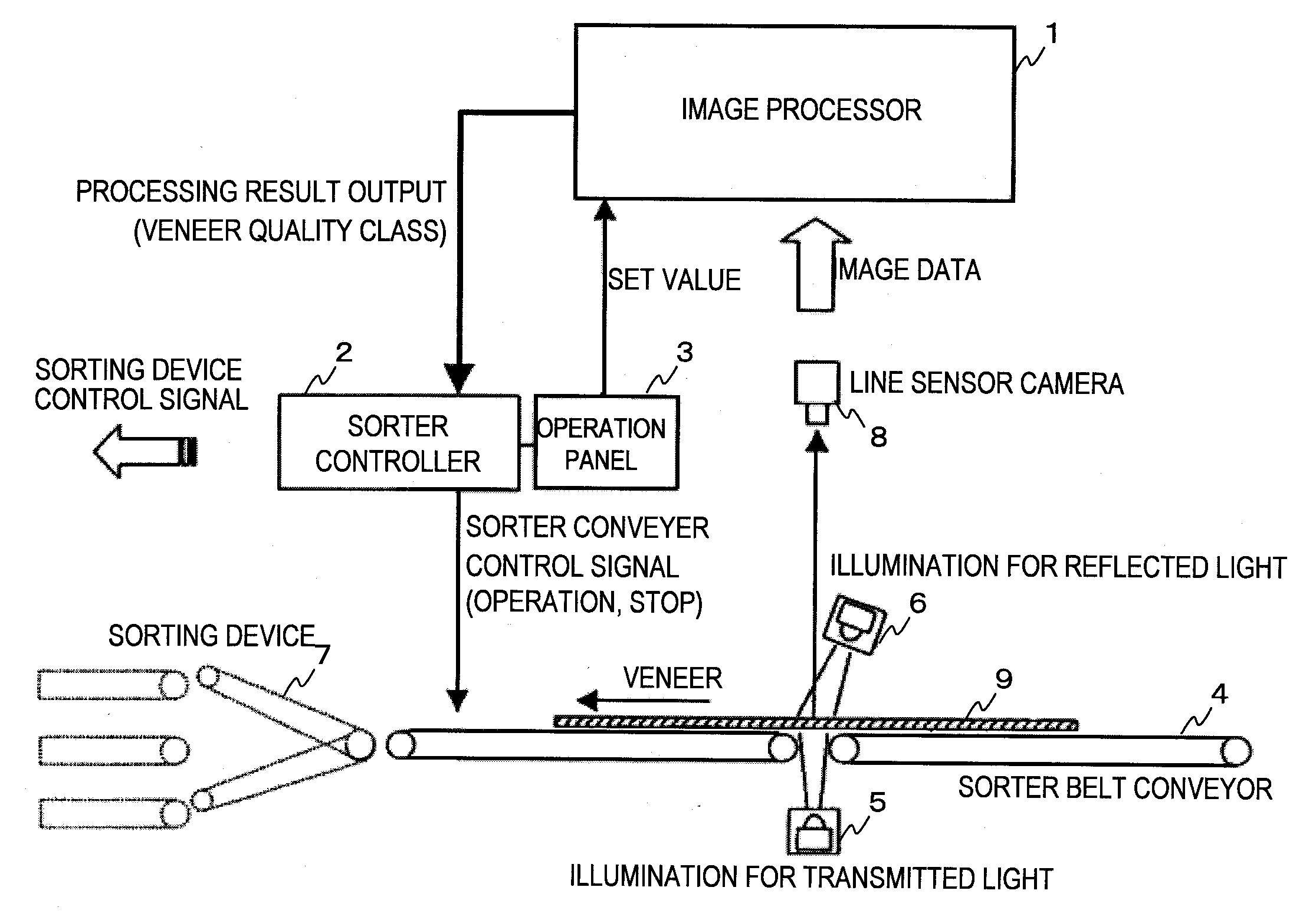
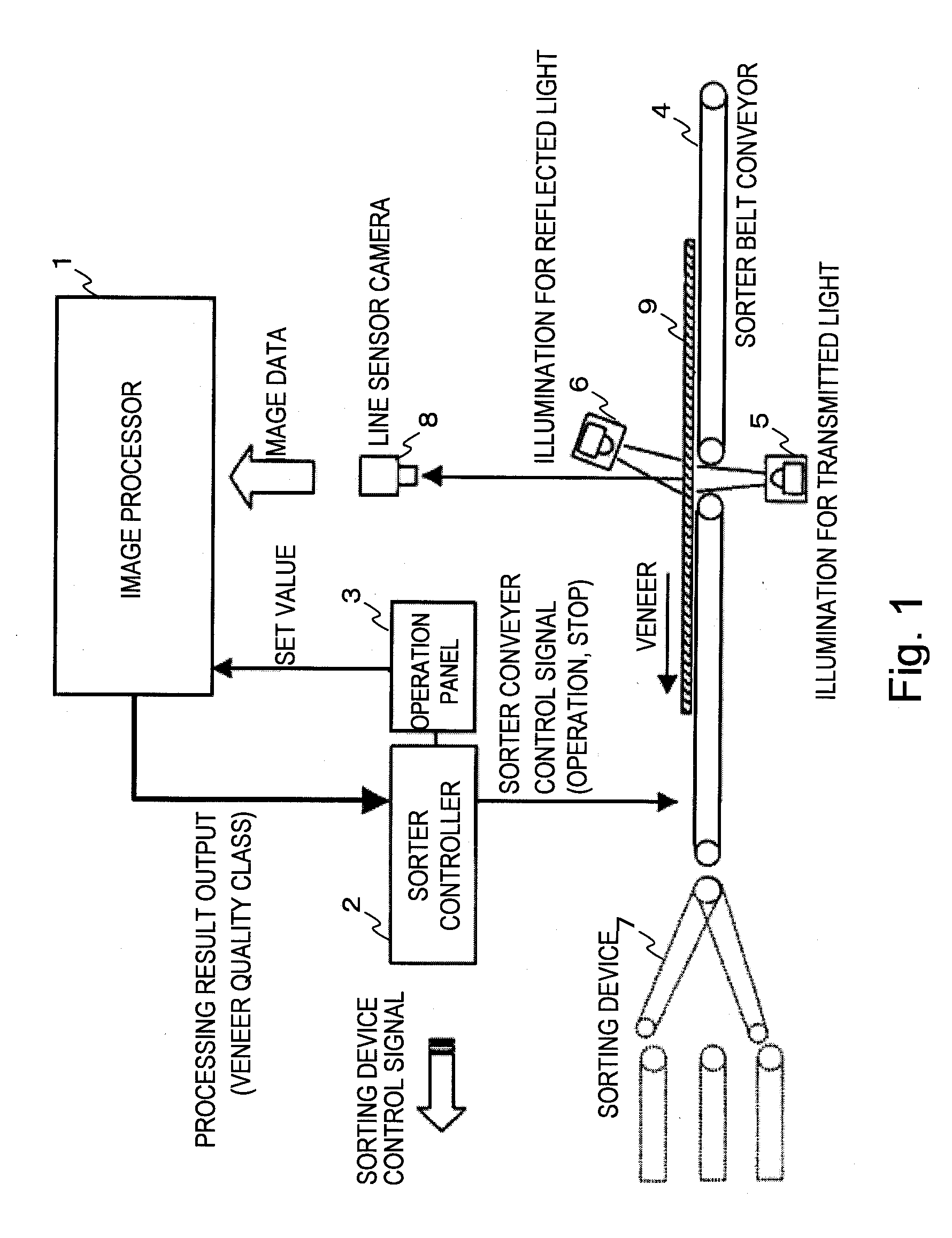
[0023]FIG. 1 is an explanatory diagram of a veneer sorter. In FIG. 1, reference numeral 1 denotes an image processor (image processing means), 2 denotes a sorter controller, 3 denotes an operation panel, 4 denotes a belt conveyor, 5 denotes an illumination for transmitted light, 6 denotes an illumination for reflected light, 7 denotes a sorting device, 8 denotes a line sensor camera (imaging means), and 9 denotes a veneer (lumber).

[0024]In order to solve the problems described above, one aspect of the present invention is configured as follows.

[0025](1) Imaging means 8 captures a color image of lumber 9. Image processing means 1 obtains a color distribution of the color image captured by the imaging means 8, compares the obtained color distribution with a predetermined color distribution of normal lumber, judges the obtained color distribution as an abnormal one when it is deviated from the color distribution of normal lumber by a predetermined value or more, and detects an area on ...


PUM


Abstract

An imaging means captures a color image of lumber. An image processing means obtains the color distribution of the color image captured by the imaging means, compares the obtained color distribution with a predetermined color distribution of normal lumber, judges the obtained color distribution as an abnormal one when it is deviated from the color distribution of normal lumber by a predetermined value or more, and detects a defect of the lumber having the abnormal color distribution deviated by a value larger than the predetermined value in an area on the surface of the lumber captured by the imaging means.

Description

CROSS-REFERENCE TO RELATED APPLICATION[0001]This application is based upon and claims the benefit of priority of the prior International application PCT / JP2007 / 058583, filed on Apr. 20, 2007, the entire contents of which are incorporated herein by reference.BACKGROUND OF THE INVENTION[0002]1. Field of the Invention[0003]The present invention relates to a lumber inspection method and device thereof for detecting defective portions due to discoloration which exist in wood-based material such as a veneer or a cut piece cut from a log of wood or the like. For example, for manufacturing plywood, a log is cut using a cutting tool to consecutively obtain veneers with a thickness of several millimeters. The veneers are then cut to a predetermined size, and after drying, several veneers are integrated through lamination using an adhesive. During such manufacturing processes, it is necessary to sort the veneers into those that will compose the outer layers of plywood or, in other words, those...

Claims


Application Information

Patent Timeline
IPC IPC(8): H04N7/18G06K9/00
CPCB27G1/00G01J3/46G01J3/462G01J3/50G06T2207/30161G01N33/46G06T7/001G06T7/408G06T2207/10024G01N21/8986G06T7/90G01B11/30G01N21/898G06T7/00
Inventor HIRAOKA, NORIYUKI
Owner MEINAN MASCH WORKS INC
Why Eureka
Try Eureka