Method for manufacturing an optical element made of thermosetting plastic material for use in eye-protecting devices and optical element thus obtained

a thermosetting plastic and manufacturing method technology, applied in the direction of optics, lenses, instruments, etc., can solve the problems of non-optimal optical characteristics of moulding, drawbacks of relatively high cost, and jeopardize the optical properties of the optical element, and achieve the effect of low cos

Inactive Publication Date: 2010-06-10
INTERCAST EURO
View PDF11 Cites 11 Cited by
  • Summary
  • Abstract
  • Description
  • Claims
  • Application Information

AI Technical Summary

Benefits of technology

[0030]The present invention aims at providing a method which allows to manufacture at the lowest possible cost an optical element made of thermosetting plastic material for use in eye-protecting devices having at least one functionalised layer adapted to modify the spectral characteristics of the transmitted light and which is devoid at least in part of the drawbacks mentioned above with reference to the cited prior art.

Problems solved by technology

The optical elements provided with at least one functionalised layer adapted to modify the spectral characteristics of the transmitted light manufactured by employing thermoplastic materials by means of injection moulding, however, possess non-optimal optical characteristics due to both the pre-selected material (for example, the polycarbonate has a rather low Abbe number), and to the injection moulding technique itself which imparts to the material during the forming operations deformations which turn out in undesired birefringence phenomena of the finished optical element.
The introduction in the optical element of a functionalised layer in the form of a laminate functional film, moreover, introduces further elements which can jeopardise the optical properties of the optical element and related to the possibility that defects may form at the interface between the laminate film and the mass of thermoplastic material, or to ageing phenomena with a partial separation of the laminate film from such a mass.
This technique, while being substantially suitable for the purpose, has however the drawback of having a relatively high cost, in particular in the case of photochromatic compounds, due to the high cost of such compounds which are employed for the mass treatment of the plastic material.
This manufacturing method, while employing thermosetting plastic materials, involves however an injection of plastic material in a molten state into the mould, and as such, has the same drawbacks illustrated above with reference to the injection moulding techniques of the thermoplastic materials.
Also in this case, moreover, the insertion in the optical element of a layer in the form of a laminate polarising film can be affected by the drawbacks related to the possibility that defects may form at the interface between the laminate film and the thermosetting material mass, or to ageing phenomena with a partial separation of the laminate film from the mass itself.
The manufacturing methods disclosed in this reference, however, are affected by a number of drawbacks.
Such a desired asymmetry of the polarising blank, however, generates a strong manufacturing problem since it may be difficult to completely fill in a proper manner the two strongly asymmetric hollow portions defined within the mould cavity by the polarising film to obtain an optical element of adequate quality avoiding at the same time a displacement of the polarising film from the desired position.
This problem, furthermore, may further worsen together with the increase of viscosity and / or casting flow rate of the thermosetting resin inside the mould.

Method used


Image

  • Method for manufacturing an optical element made of thermosetting plastic material for use in eye-protecting devices and optical element thus obtained
  • Method for manufacturing an optical element made of thermosetting plastic material for use in eye-protecting devices and optical element thus obtained
  • Method for manufacturing an optical element made of thermosetting plastic material for use in eye-protecting devices and optical element thus obtained

Examples


example 1

Manufacturing of a Non-Polarising Optical Element

[0361]A bicomponent thermosetting polyurethane resin comprising:

[0362]Component A: polyurethane liquid prepolymer having an isocyanate group content of 11%, commercially available from Simula Inc. with the trade name of SIM2020, including UV absorber Uvinul® 3049 (BASF) at the concentration of 0.3% by weight, and

[0363]Component B: 1-methyl-3,5-diethyl-2,4- and / or -2,6-diaminobenzene (also known as 3,5-diethyl-2,4-and / or-2,6-toluenediamine) or DETDA available from Alberarle with the commercial name Ethacure® 100,

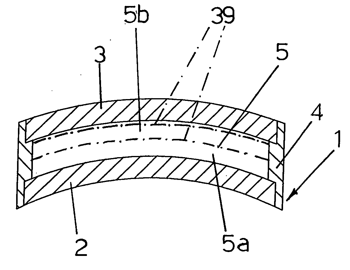
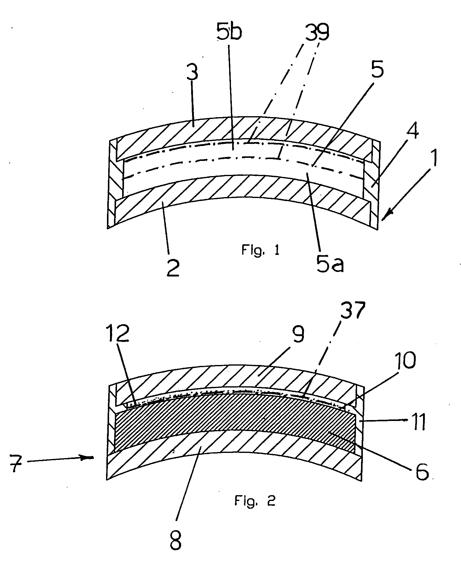
[0364]is cast into the cavity 5 of the mould 1 illustrated in FIG. 1 and partially cross-linked at 120° C. by means of a heat cycle of 60 minutes.

[0365]The partially cross-linked optical part thus obtained (layer 6) is then extracted from the mould 1 and the partial cross-linking is verified by observing the presence of unreacted isocyanate groups by means of known FT-IR analysis techniques.

[0366]The partially cross-linked opti...

example 2

Manufacturing of a Non-Polarising Optical Element

[0372]A bicomponent thermosetting polyurethane resin comprising:

[0373]Component A: polyurethane liquid prepolymer having an isocyanate group content of 11%, commercially available from Simula Inc. with the trade name of SIM2020, including UV absorber Uvinul® 3049 (BASF—0.3% by weight), and

[0374]Component B: DETDA available from Albemarle with the commercial name Ethacure® 100,

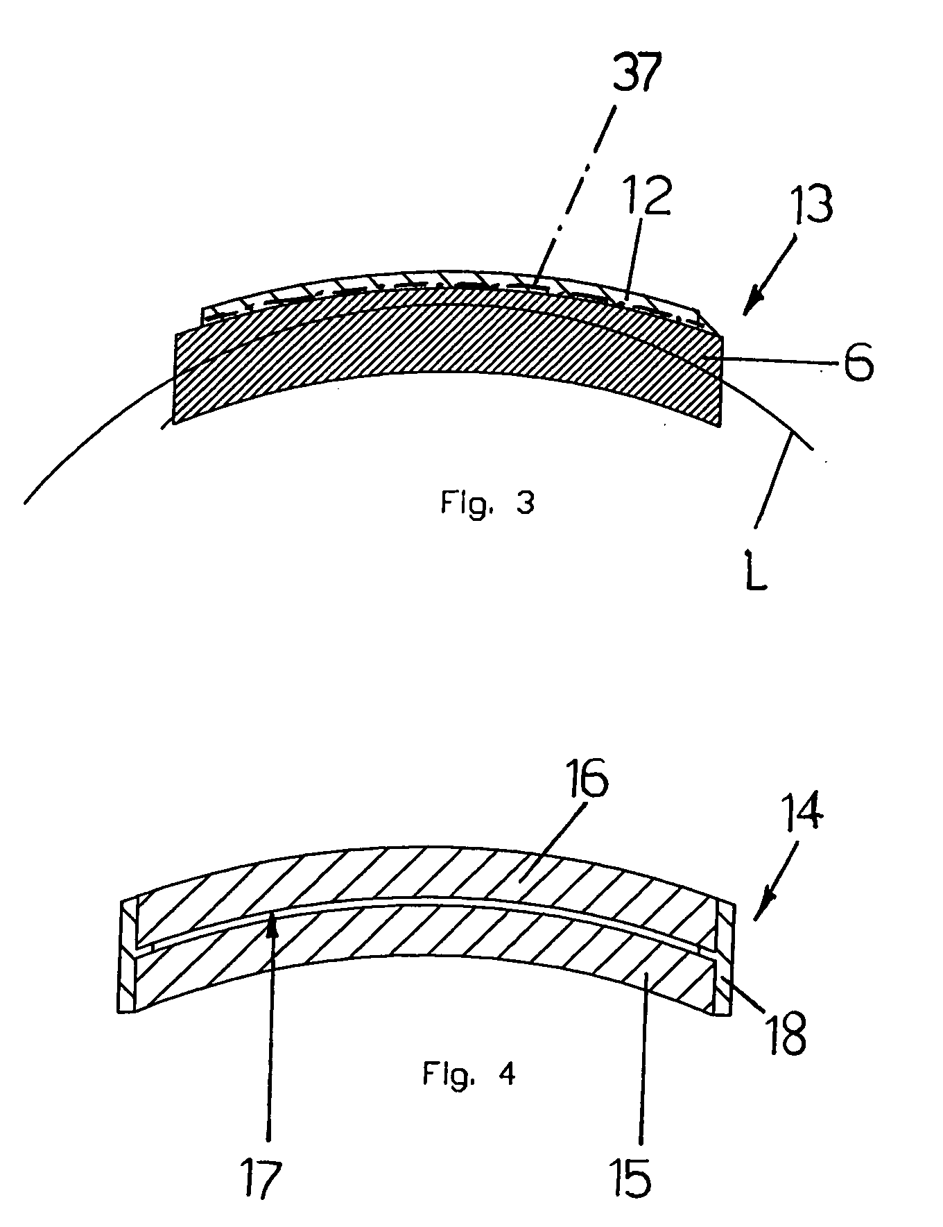
[0375]is cast into the cavity 17 of the mould 14 illustrated in FIG. 4 and partially cross-linked at 120° C. by means of a heat cycle of 60 minutes.

[0376]The partially cross-linked optical part thus obtained (layer 19) is then extracted from the mould 14 and the partial cross-linking is verified by observing the presence of unreacted isocyanate groups by means of known FT-IR analysis techniques.

[0377]A portion of the partially cross-linked optical part (layer 19) is then dyed by means of heat transfer in liquid phase by immersing the partially cross-linked optica...

example 3

Manufacturing of a Polarising Optical Element

[0384]A bicomponent thermosetting polyurethane resin comprising:

[0385]Component A: polyurethane liquid prepolymer having an isocyanate group content of 11%, commercially available from Simula Inc. with the trade name of SIM2020, including UV absorber Uvinul® 3049 (BASF) at the concentration of 0.3% by weight, and

[0386]Component B: 1-methyl-3,5-diethyl-2,4- and / or -2,6-diaminobenzene (also known as 3,5-diethyl-2,4-and / or -2,6-toluenediamine) or DETDA available from Alberarle with the commercial name Ethacure® 100,

[0387]is cast into the cavity 5 of the mould 1 illustrated in FIG. 1 and partially cross-linked at 120° C. by means of a heat cycle of 60 minutes.

[0388]The partially cross-linked optical part thus obtained (layer 6) is then extracted from the mould 1 and the partial cross-linking is verified by observing the presence of unreacted isocyanate groups by means of known FT-IR analysis techniques.

[0389]The partially cross-linked optical...


PUM

PropertyMeasurementUnit
temperatureaaaaaaaaaa

Abstract

A method is described for manufacturing an optical element (13) made of thermosetting plastic material comprising the steps of: a) positioning in a mould a first self-supporting layer (6) made of partially cross-linked thermosetting plastic material including reactive functional groups; b) forming, on at least one surface of the self-supporting layer (6), a second layer (12) including: i) a polymerisable material in liquid phase including: prepolymers and/or monomers including reactive functional groups capable of chemically reacting with the reactive functional groups of the self-supporting layer made of partially cross-linked thermosetting plastic material, a reactive component including functional groups capable of chemically reacting with the reactive functional groups of the prepolymers and/or of the monomers and optionally with the reactive functional groups of the self-supporting layer (6) made of partially cross-linked thermosetting plastic material; ii) at least one element adapted to modify the spectral characteristics of the transmitted light; and c) cross-linking said first (6) and second (12) layers in the mould, so as to form a solid monolithic optical element (13) made of thermosetting plastic material comprising at least one functionalised layer (12) adapted to modify the spectral characteristics of the transmitted light. The optical element (13) thus obtained may have polarising properties, has optimal optical and mechanical characteristics and is capable at the same time of modifying the spectral characteristics of the transmitted light as desired.

Description

BACKGROUND OF THE INVENTION[0001]In a general aspect thereof, the present invention relates to the manufacture of an optical element made of a thermosetting plastic material for use in eye-protecting devices and / or in devices adapted for correcting vision, such as eyeglasses, masks, visors and the like.[0002]More particularly, the invention relates to a method for manufacturing a polarising or non-polarising optical element comprising at least one functionalised layer adapted to modify the spectral characteristics of transmitted light as well as to a polarising or non-polarising optical element thus obtained.[0003]The invention also relates to any eye-protecting device comprising the aforementioned polarising or non-polarising optical element.[0004]The optical element of the invention can be a semi-finished product in terms of shape and / or refractive properties, from which it is possible to obtain, by shaping and possibly bevelling, an ocular for eye-protecting devices, such as for ...

Claims


Application Information

Patent Timeline
Patent Type & Authority Applications(United States)
IPC IPC(8): G02C7/12B29D11/00
CPCB29D11/0073B29D11/00528B29D11/00413
Inventor MENTA, FEDERICOLAGASI, MATTEOMARUSI, GRAZIANO
Owner INTERCAST EURO
Why Eureka
Try Eureka