Liquid optical lens and liquid optical lens modules

a liquid optical lens and liquid optical technology, applied in the field of optical lenses and liquid optical lens modules, can solve the problems of high price, low zooming speed, and high electricity consumption, and achieve the effect of reducing the effect of liquid materials on zooming

Inactive Publication Date: 2010-06-10
IND TECH RES INST
View PDF7 Cites 12 Cited by
  • Summary
  • Abstract
  • Description
  • Claims
  • Application Information

AI Technical Summary

Benefits of technology

[0011]Accordingly, the present invention provides a liquid optical lens having an elastic membrane as an interface between a first liquid and a second liquid to reduce the effect of liquid materials on zooming.
[0017]In summary, the liquid optical lens of the present invention uses the elastic membrane as the interface between the first liquid and the second liquid, thereby preventing the first liquid and the second liquid from mixing due to temperature changes. In addition, the liquid optical lens module of the present invention utilizes the volume adjustment mechanism to modify the volume ratio between the first liquid and the second liquid, and consequently manipulates the curvature of the elastic membrane to achieve lens focusing. Different from the conventional electrowetting method, the present invention can reduce the effect of liquid materials on the lens curvature focusing and elevate its focusing performance. The liquid optical lens and the liquid optical lens module of the present invention have simple structures and can achieve nano-meter level demands.

Problems solved by technology

The conventional step motors used to drive the lens focus positioning device have many problems, such as large volume, complicated mechanism, loud noise, slow zooming speed, high electricity consumption (about 300 mW to 600 mW) and high price, all of which make them unsuitable for current use.
However, the electricity consumption is still high when the voice coil motors are used to position the lens for a long period.
Thus, the miniaturization of the optical lens modules is unfavorable.
However, the aforementioned zooming driving mode using the piezoelectric motor still needs lens movement and consequently cooperation with the lens moving elements.
More specifically, the lens moving space needs to be disposed firstly, which has an adversely effect on the miniaturization of the optical lens modules.
However, the liquid materials are hard to be managed such that many problems still present in the current liquid zooming driving mode.
Firstly, environmental temperature enormously affects liquid zooming.
In detail, once the temperature changes, the silicon oil and the water may each change its density and mix together, which results in coma.
Moreover, by changing the liquid contacting angle with the applied voltage, the voltage applied may electrolyze the silicon oil and the water and result in degeneration of the silicon oil and the water.
Furthermore, when adjusting the zooming interface, the silicon oil and the water moves and generates friction with an inner wall of the lens.
After long period of operation, a hysteresis is generated between the silicon oil, the water and the inner wall of the lens, which leads to a problem of asymmetric zooming interface.
However, this cannot completely solve the problem of the liquid lens that uses the liquid zooming.

Method used


Image

  • Liquid optical lens and liquid optical lens modules
  • Liquid optical lens and liquid optical lens modules
  • Liquid optical lens and liquid optical lens modules

Examples


first embodiment

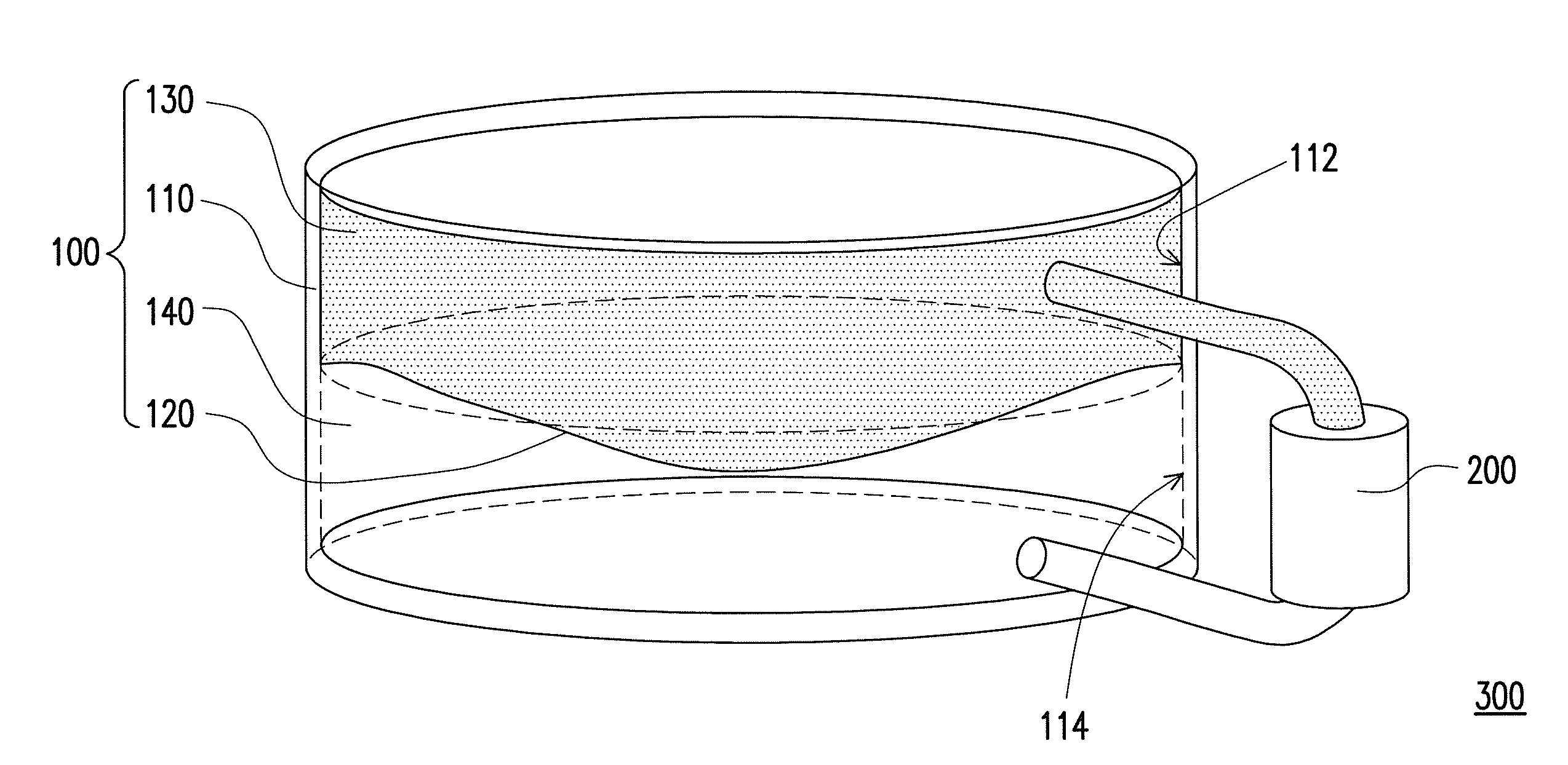
[0042]FIG. 3A is a perspective view of a liquid optical lens module according to a first embodiment of the present invention. FIG. 3B is a side view and a magnified view of a volume adjustment mechanism in FIG. 3A. In a liquid optical lens module 302, the same elements as those in FIG. 2 are labeled with the same numbers, thus the detailed structural composition will not be repeated herein. A volume adjustment mechanism 200a is illustrated in the following.

[0043]Referring to FIG. 3A and FIG. 3B, the volume adjustment mechanism 200a includes a liquid carrier 210, a bimorph device 220, a first pipe 230, and a second pipe 240. The bimorph device 220 is disposed within the liquid carrier 210 and has a fixed end 220a and a free end 220b. The fixed end 220a is connected to the liquid carrier 210 while the free end 220b moves back and forth along the interior of the liquid carrier 210. The bimorph device 220 divides the liquid carrier 210 into a first region 212 and a second region 214. Th...

second embodiment

[0047]FIG. 4A is a perspective view of a liquid optical lens module according to a second embodiment of the present invention. FIG. 4B is a side view and a magnified view of a volume adjustment mechanism in FIG. 4A. In a liquid optical lens module 304, the same elements as those in FIG. 2 are labeled with the same numbers, thus the detailed structural composition will not be repeated herein. A volume adjustment mechanism 200b is illustrated in the following.

[0048]Referring to FIG. 4A and FIG. 4B simultaneously, the volume adjustment mechanism 200b includes a liquid carrier 210, a spacer 260, an actuator 270, a first pipe 230, and a second pipe 240. The liquid carrier 210 has a pivot 210a. The spacer 260 is disposed within the liquid carrier 210. The spacer 260 includes a pivotal end 260a and a free end 260b. The pivotal end 260a is connected to the pivot 210a, and the free end 260b moves back and forth along the interior of the liquid carrier 210. The spacer 260 divides the liquid c...

third embodiment

[0052]FIG. 5A is a perspective view of a liquid optical lens module according to a third embodiment of the present invention. FIG. 5B is a magnified view of a volume adjustment mechanism in FIG. 5A. In a liquid optical lens module 306, the same elements as those in FIG. 2 are labeled with the same numbers, thus the detailed structural composition will not be repeated herein. A volume adjustment mechanism 200d is illustrated in the following.

[0053]Referring to FIG. 5A and FIG. 5B, the volume adjustment mechanism 200d includes a liquid carrier 210, a piston device 280, a linkage 290, an actuator 270, a first pipe 230, and a second pipe 240. The piston device 280 is disposed within the liquid carrier 210 and divides the liquid carrier 210 into a first region 212 and a second region 214. The linkage 290 has a pivotal end 290a and a driving end 290b. The pivotal end 290a is connected to the piston device 280. The actuator 270 is connected to the driving end 290b to drive the linkage 290....


PUM


Abstract

A liquid optical lens, including a transparent container, an elastic membrane, a first liquid and a second liquid, is provided. The transparent container is divided into a first chamber and a second chamber by the elastic membrane. The first liquid fills the first chamber. The second liquid fills the second chamber. The curvature of the elastic membrane is regulated by changing the volume ratio between the first liquid and the second liquid, so as to adjust the focal length of the liquid optical lens. Moreover, a liquid optical lens module including the above liquid optical lens and a volume adjustment mechanism is also provided. The focal length of the liquid optical lens can be precisely adjusted by using the volume adjustment mechanism.

Description

CROSS-REFERENCE TO RELATED APPLICATION[0001]This application claims the priority benefit of Taiwan application serial no. 97147875, filed on Dec. 9, 2008. The entirety of the above-mentioned patent application is hereby incorporated by reference herein and made a part of specification.BACKGROUND OF THE INVENTION[0002]1. Field of the Invention[0003]The present invention relates to an optical lens and an optical lens module. More particularly, the present invention relates to a liquid optical lens and a liquid optical lens module.[0004]2. Description of Related Art[0005]Lens modules, applied in digital camera and camera phone industries, need a precise and compact lens focus positioning device. Well-known international companies such as Samsung, Seiko, Epson, Varioptic and Squiggle have established numerous researches on the development of the lens focus positioning device. Currently, the driving modes of the lens focus positioning device can be classified into four types, such as ste...

Claims


Application Information

Patent Timeline
Patent Type & Authority Applications(United States)
IPC IPC(8): G02B3/14G02B1/06
CPCG02B3/14
Inventor CHOU, CHUN-HUNGCHUNG, YU-LIANGTZOU, HORN-SEN
Owner IND TECH RES INST
Why Eureka
Try Eureka