

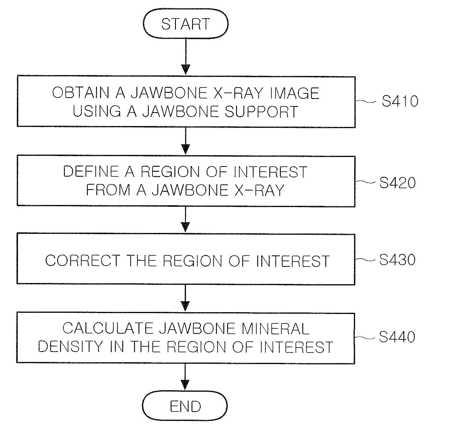
Method and support device for measuring jawbone mineral density
a technology of supporting device and jawbone, which is applied in the direction of instruments, tubes with screens, and enhancement of images, etc., can solve the problems of difficult effective restoration of decreased bone quantity, high radiation dose, and high cost of qct equipment, so as to improve the accuracy of jawbone mineral density measuremen
- Summary
- Abstract
- Description
- Claims
- Application Information
AI Technical Summary
Benefits of technology
Problems solved by technology
Method used
Image

Examples
Embodiment Construction
[0031]Exemplary embodiments of the present invention will now be described in detail with reference to the accompanying drawings. For the exemplary embodiments of the present invention, detailed descriptions of known functions and constructions that are related to the present invention are omitted for clarity when they are proven to make the gist of the present invention unnecessarily confusing.
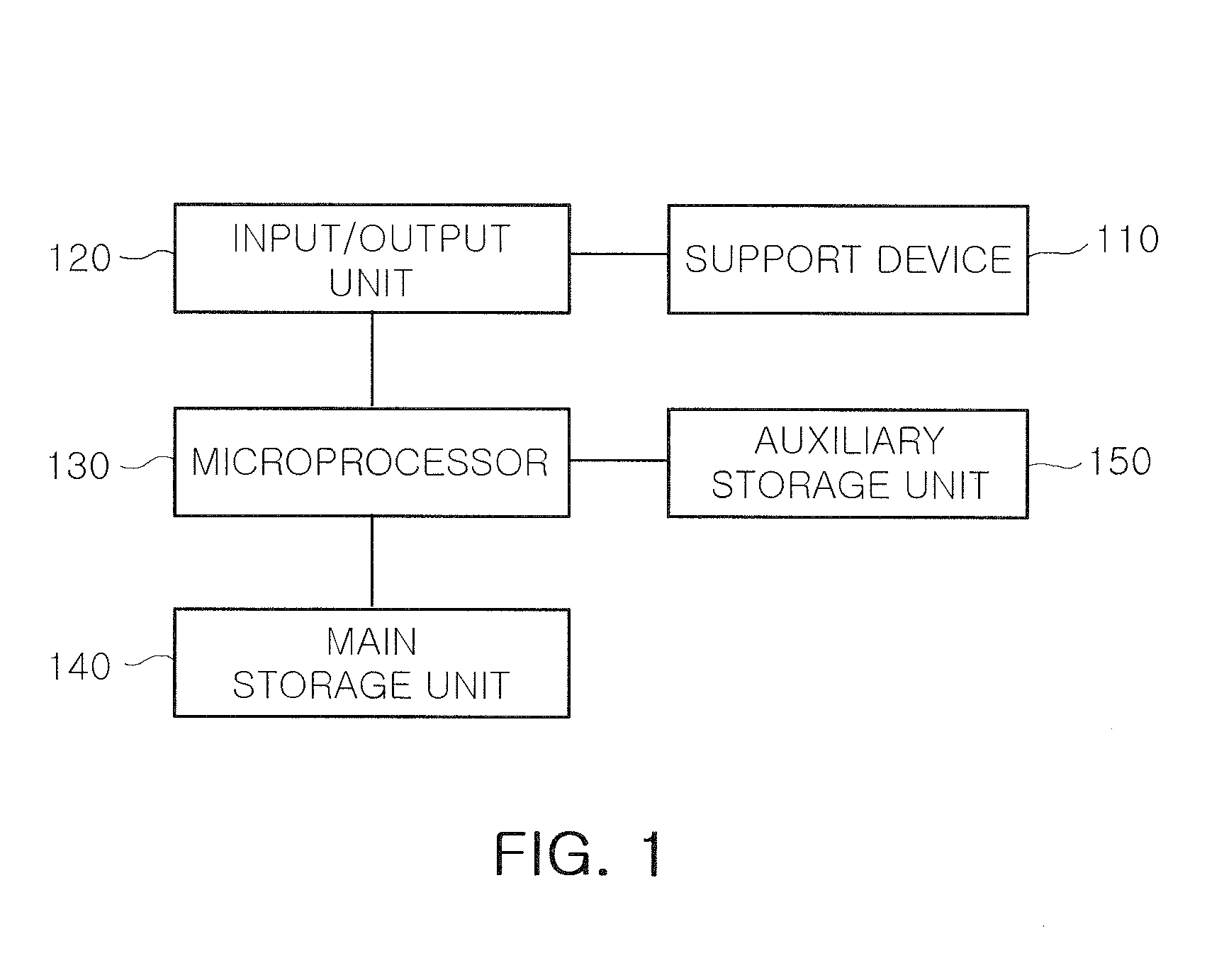
[0032]FIG. 1 is a diagram illustrating a configuration of a system for measuring jawbone mineral density according to one exemplary embodiment of the present invention.
[0033]The system for measuring jawbone mineral density as shown in FIG. 1 includes a support device 110 for measuring jawbone mineral density, an input / output unit 120 for inputting / outputting data that are required to measure jawbone mineral density, a main storage unit 140 and an auxiliary storage unit 150 for storing information that is required to measure jawbone mineral density, and a microprocessor 130 controlling operati...
PUM
| Property | Measurement | Unit |
|---|---|---|
| thickness | aaaaa | aaaaa |
| heights | aaaaa | aaaaa |
| heights | aaaaa | aaaaa |
Abstract
Description
Claims
Application Information