Reference Clock Rate Detection for Variable Rate Transceiver Modules

Inactive Publication Date: 2010-06-10
MACOM CONNECTIVITY SOLUTIONS LLC
View PDF27 Cites 50 Cited by
  • Summary
  • Abstract
  • Description
  • Claims
  • Application Information

AI Technical Summary

Benefits of technology

[0009]A single module type with multiple data rate capability does not have to be preset to function at a fixed rate port configuration. Such a module is pluggable in all port configurations of different da

Problems solved by technology

However, this is not the case, as modules and system platforms do not communicate, data rate information between each other.
One undesirable alternative is a system platform that provides a single data rate that is not standardized among all platform developers and module vendors.
However, this capability would add to the cost and complexity of the units.
However, as mentioned above, no p

Method used


Image

  • Reference Clock Rate Detection for Variable Rate Transceiver Modules
  • Reference Clock Rate Detection for Variable Rate Transceiver Modules
  • Reference Clock Rate Detection for Variable Rate Transceiver Modules

Examples


Embodiment Construction

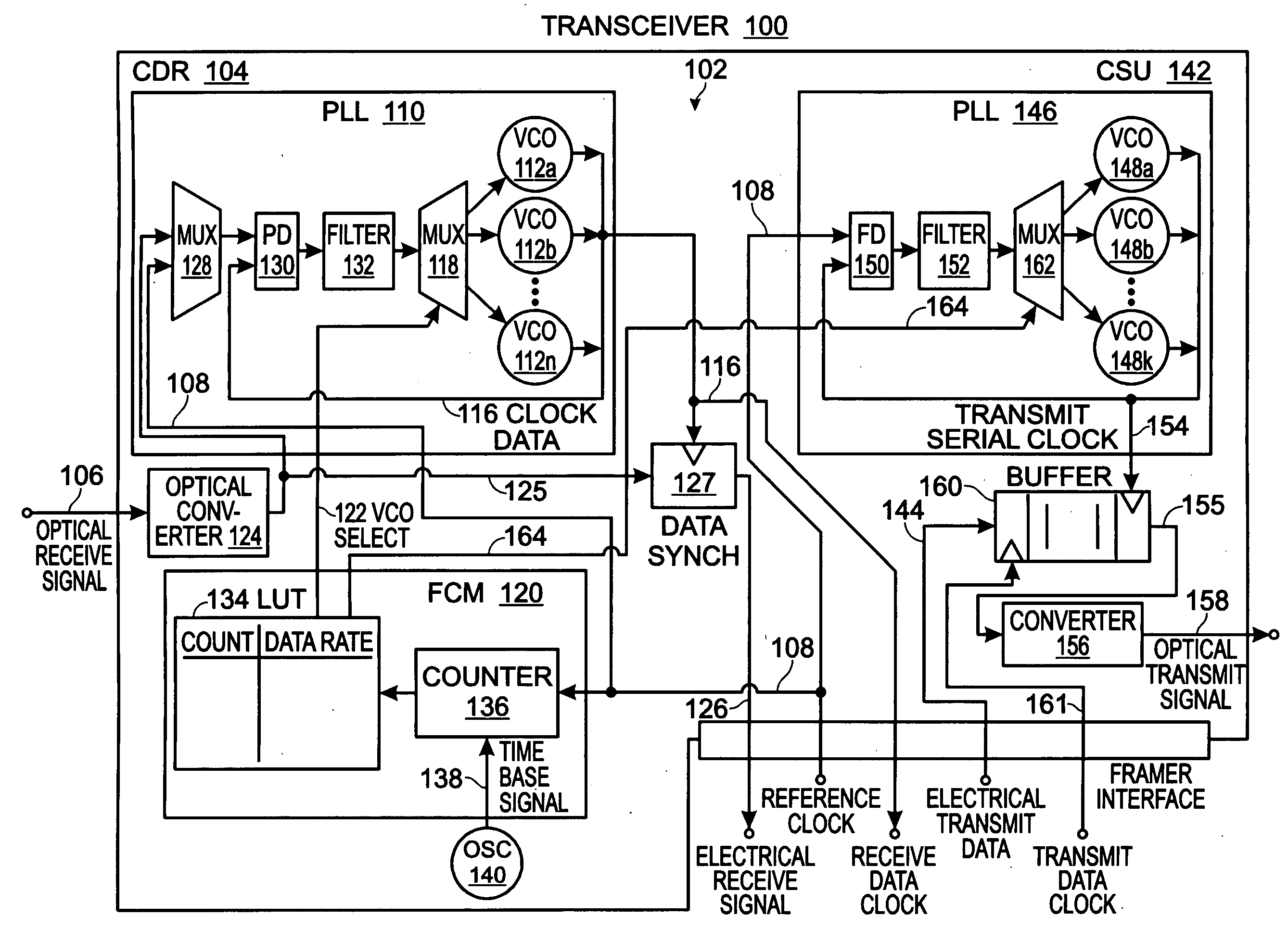
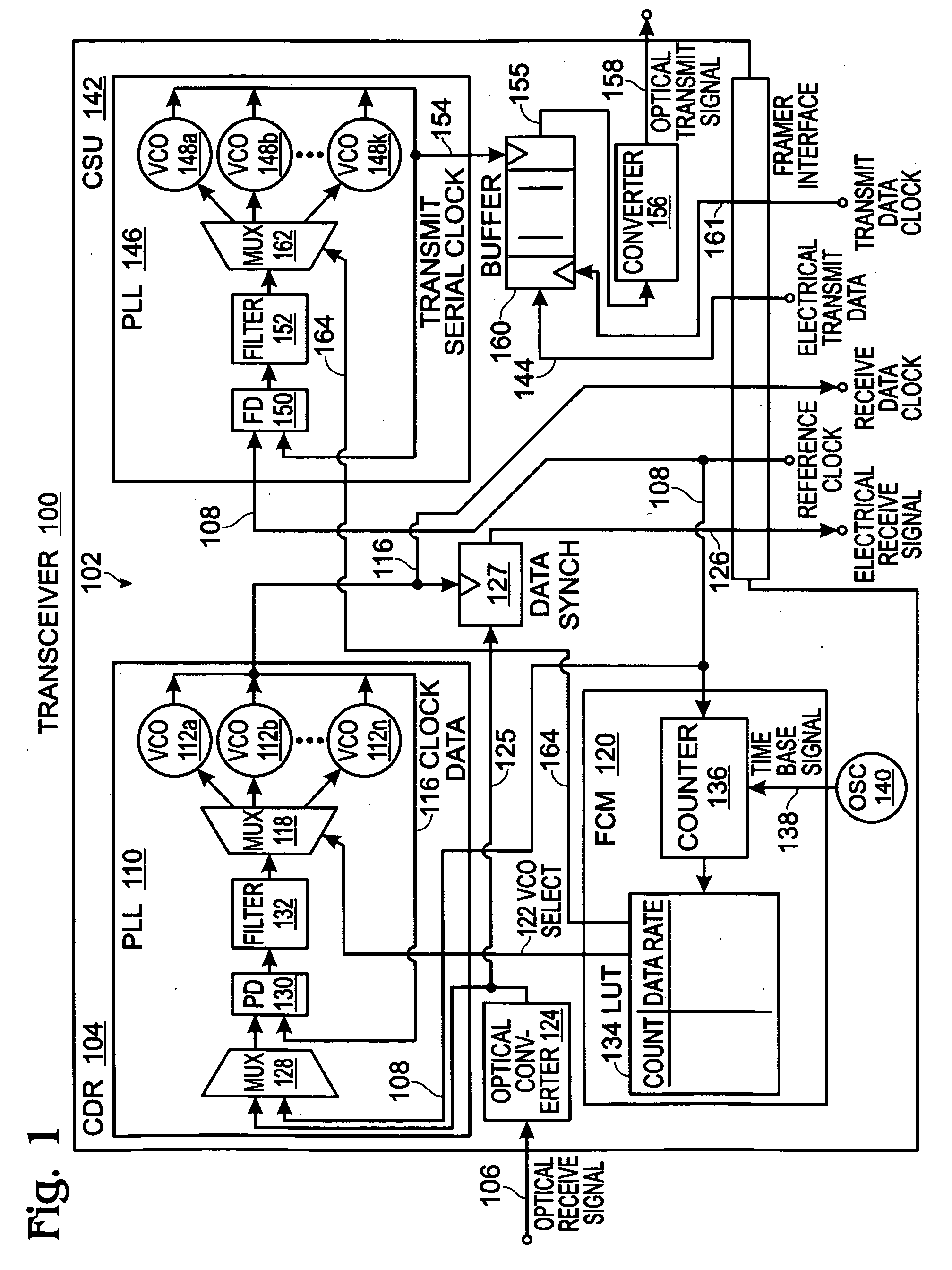
[0019]FIG. 1 is a schematic block diagram of an optical / electrical transceiver 100 with a system for determining an optical signal frequency range. The system 102 comprises a clock data recovery (CDR) unit 104 having network interface on line 106 to accept an optical receive signal having a non-predetermined data rate. The CDR 104 also has a framer interface to accept an electrical reference clock signal on line 108 having a non-predetermined frequency. The CDR 104 further comprises a phase-locked loop (PLL) 110 including a selectable voltage controlled oscillator (VCO) 112 to supply an electrical receive data clock on line 116 via the framer interface. In one aspect, the CDR PLL 110 includes a plurality of VCOs with a corresponding plurality of unique output frequency ranges, selectively engagable in response to a VCO selection signal. Typically, the VCOs have overlapping output frequency ranges. VCOs 112a through. 112n are shown, selectable through multiplexer (MUX) 118. Note: n i...


PUM


Abstract

A system and method are provided for determining an optical signal frequency range in an optical/electrical transceiver. The method receives an optical receive signal having a non-predetermined data rate via a network interface, and also receives an electrical reference clock signal having a non-predetermined frequency via a framer interface. The reference clock signal frequency is cross-referenced to an optical receive signal frequency. In one aspect a clock and data recovery (CDR) voltage controlled oscillator (VCO) is selected having an output frequency matching the cross-referenced optical receive signal frequency. The optical receive signal is converted to an electrical receive signal. Initially, the VCO is frequency-locked to the reference clock. Subsequent to frequency-locking the VCO output frequency, the converted optical signal is phase-locked, generating a receive data clock. The CDR supplies a converted optical receive signal and receive data clock to the framer interface.

Description

BACKGROUND OF THE INVENTION[0001]1. Field of the Invention[0002]This invention generally relates to digital communications and, more particularly, to a system and method for clock rate detection in clock and data recovery (CDR) and clock synthesis units (CSUs).[0003]2. Description of the Related Art[0004]Conventionally, system platforms provide an optical transceiver module with a reference clock and data at the reference clock multiplied rate. These rates are a selection of more than half a dozen rates which continue to increase as technology moves forward. The module is required to operate at the given data rate without any system setup communication. If this setup communication protocol was provided and all modules and systems spoke this protocol, then data rate acquisition would be relatively easy. However, this is not the case, as modules and system platforms do not communicate, data rate information between each other.[0005]Some prior art CDR and CSUs optical interface data ra...

Claims


Application Information

Patent Timeline
IPC IPC(8): H04B10/00H04B10/04
CPCH04B10/40H04L2027/0073H04L7/033H04B10/69
Inventor PEREZ, RONALD EDWARD
Owner MACOM CONNECTIVITY SOLUTIONS LLC
Why Eureka
Try Eureka