Connector arrangement for a medium-conducting, electrically-heatable hose

Active Publication Date: 2010-06-10
CONTITECH SCHLAUCH
3 Cites 24 Cited by

AI-Extracted Technical Summary

Problems solved by technology

It is disadvantageous that the exposed ends of the heating conductor, which are of a predefined length, are virtually completely unprotected from the point where they emerge from the hose up to their connecting point.
This risk of freezing occurs, in particular, in exhaust gas post-treatment systems for reducing nitrogen oxide emissions of an internal combustion engine.
The hose lines between the reservoir container and the exhaust gas line have to be capable of being heated, since below −11° C. there is a risk of ...

Benefits of technology

[0019]It is an object of the invention to provide a connector arrangement of the type described initially herein wherein the entire line branch, that is to say the hose and the connecting points of ...

Abstract

A connector arrangement connects an electrically-heatable hose to a piece of equipment. The connector arrangement is configured as a plug connection wherein the hose has a first plug connector which can be plugged into a mating second plug connector mounted on the piece of equipment. The hose has at least one heater lead embedded in the hose and the heater lead has an end segment brought out of the hose for fitting with the first plug connector. The first plug connector includes a body having an annular housing region defining an end. A connector stub is arranged on the end for receiving an end portion of the hose thereon. An annular receptacle is pushed onto the annular housing region and has a surface and a helical slot formed in the surface. The end segment of the heater lead is helically placed in the helical slot so as to spirally cover over the annular housing region.

Application Domain

Pipe heating/coolingMachines/engines +4

Technology Topic

Extremity PartEngineering +1

Image

  • Connector arrangement for a medium-conducting, electrically-heatable hose
  • Connector arrangement for a medium-conducting, electrically-heatable hose
  • Connector arrangement for a medium-conducting, electrically-heatable hose

Examples

  • Experimental program(1)

Example

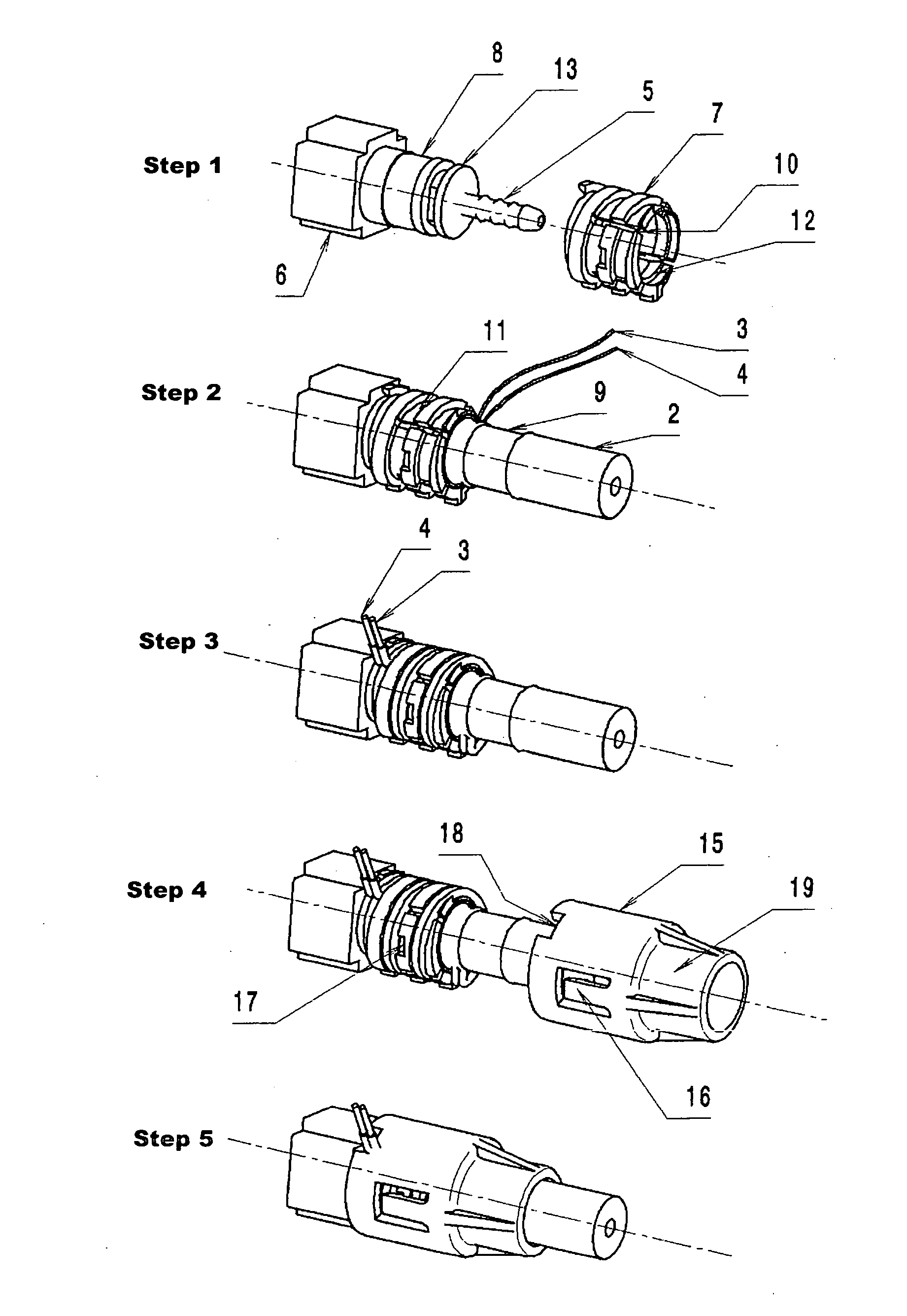
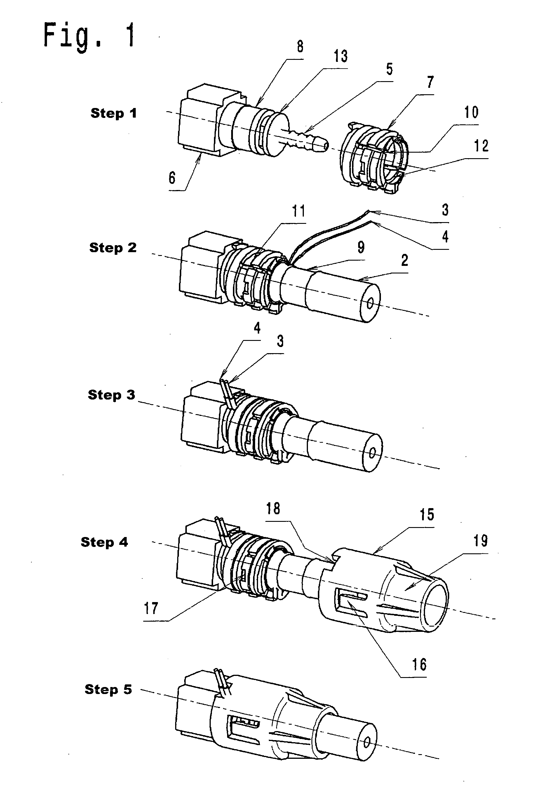
[0034]The plug connector is shown in five assembly steps in FIG. 1 and receives the end of an electrically-heatable hose 2. After the hose end has been fitted on an assembly (not shown), for example a reservoir tank, an injection unit, a pump et cetera, which has a male plug connector already mounted as a mating part, the connector arrangement, which is configured with a female quick-action plug connector 6 as a main component, is mounted by simple plugging in. The female plug structure cannot be seen in the perspective illustration and lies opposite the connector element 5.
[0035]The hose 2, which is shown with only a short segment, is heated with two coiled heating conductors or leads 3 and 4, often also referred to as heating stranded conductors, which are integrated into the hose structure. For the fitting of the electrical plugs (not shown here), the individual heating conductors 3 and 4 are exposed at the end of the hose 2. The two heating conductors 3 and 4 here are exposed at the end of the hose over a somewhat greater length than would be required if the fitting of the plug had followed directly. The hose element which is conductor free as a result is cut off.
[0036]A cylindrical heating conductor receptacle 7 is then pushed over the connector element 5 of the standard quick-action plug connector 6 and onto a cylindrical region 8 of the plug connector housing (step 1). The cylindrical heating conductor receptacle 7 is embodied so as to be spring biased at the circumference by virtue of axial, non-through slots 10, and after being pushed on, the receptacle 7 latches with a circumferentially-extending rib 12, which is configured at one end in the inner periphery, behind a collar 13 forming an undercut. The collar 13 is part of the quick-action plug connector 6.
[0037]The hose 2 is then pushed with its hose end onto a connector stub 5 of the plug connector 6. A wraparound ring 9 is pressed onto the hose 2 to secure it to the connector stub 5 (step 2).
[0038]The free ends of the two heating conductors 3 and 4 are coiled into a single helical groove 11 in the outer surface of the heating conductor receptacle 7 (step 3). The heating conductor receptacle 7 can also be configured as a multi-groove receptacle for the heating conductors.
[0039]In order to secure this assembly, a protective sheath 15, which is partitioned along an axial plane if appropriate, is pushed over the heating conductor receptacle 7 (step 4). This protective sheath 15 is constructed in such a way that it latches to the heating conductor receptacle 7 with two latching tongues 16 engaging cutouts 17 disposed along the circumference. The assembly therefore can no longer slip (step 5). The protective sheath 15 has a cutout 18 on the front end face thereof which is open toward the plug connector.
[0040]The conductors 3 and 4 heating the plug connector 6 are covered by the protective sheath 15. The heating conductors 3 and 4 are protected and insulated and project out of the protective sheath 15 only with their connecting ends.
[0041]If hoses having only a very small diameter are used, the connector stub 5, which is embodied as a hose connector element, has correspondingly very thin walls and is therefore very fragile. Under certain conditions (high transverse force), the connector stub 5 can break off at the junction with the plug connector housing.
[0042]In order to relieve the connector stub 5 of load, the protective sheath 15 is extended in length by a cylindrical part 19 which has a somewhat larger inner diameter than the outer diameter of the surrounded hose 2. At the other end, the cylindrical part of the protective sheath 15 rests on the outer periphery of the heating conductor receptacle 7. If the hose 2 is subjected to load, the protective sheath 15 absorbs the transverse forces and conducts them directly into the plug connector housing 6.
[0043]The modified connecting arrangement, which is shown in five assembly steps in FIG. 2, receives the end of an electrically-heatable hose 2. Parts identical to those in FIG. 1 are provided with the same reference numbers below.
[0044]The hose 2 is heated with two coiled heating conductors 3 and 4 which are integrated into the hose structure. In order to fit the electrical plugs (not shown here), the individual heating conductors 3 and 4 are exposed at the end of the hose 2. In this context, the two heating conductors 3 and 4 at the hose end are exposed over a somewhat greater length than would be required if fitting of the plug had followed directly. The hose piece, which is conductor free as a result, is cut off.
[0045]The hose 2 is pushed with its hose end onto a connector stub (not shown here) of a 90° standard quick-action plug connector 26.
[0046]Thereafter, a wraparound ring 9 is pressed onto the hose 2 in order to secure it onto the connector stub.
[0047]A heating conductor receptacle 27, which in terms of circumference does not comprise a complete cylindrical circumference but rather only 190° to 200°, is pushed from above onto the cylindrical region 8 of the housing of the 90° quick-action plug connector 26.
[0048]The free ends of the two heating conductors 3 and 4 are coiled into a single helical groove 11 in the outer surface of the heating conductor receptacle 27. The heating conductor receptacle 27 can also be configured as a multi-groove receptacle for the heating conductors 3 and 4.
[0049]In order to secure this assembly, a right-angled protective sheath 36 is pushed over the heating conductor receptacle 27 and latches at the periphery with two axial latching tongues 31 into the heating conductor receptacle 27. The protective sheath 36 is held tight in a position-oriented manner on the plug connector 26 by a locking element 32, which engages from below in a guide 33 on the downward-bent leg 34 of the protective sheath 36, and which latches into the protective sheath 36 in diametrically opposite peripheral cutouts 35.
[0050]If hoses with a very small diameter are used, the connector stub, which is embodied as a hose connector element, correspondingly has very thin walls and is therefore very fragile. Under certain conditions (high lateral force), the connector element can break off at the junction with the housing.
[0051]In order to relieve the connector stub in terms of forces, the protective sheath 36 is extended with a part 34 which is open in the form of a semi-cylindrical shell. The part 34 has a somewhat larger inner diameter than the outer diameter of the surrounded hose 2. Lateral forces can be absorbed by the positively-engaging connection of the protective sheath 36 to the locking element 32, and can be applied directly to the plug connector housing.
[0052]It is understood that the foregoing description is that of the preferred embodiments of the invention and that various changes and modifications may be made thereto without departing from the spirit and scope of the invention as defined in the appended claims.
LIST OF REFERENCE NUMERALS
(Part of the Description)
[0053]2 Electrically-heatable hose
[0054]3 Heating conductor
[0055]4 Heating conductor
[0056]5 Connector stub
[0057]6 Plug connector
[0058]7 Heating conductor receptacle
[0059]8 Cylindrical housing area
[0060]9 Wraparound ring
[0061]10 Axial slots
[0062]11 Single helical groove
[0063]12 Peripherally-extending rib
[0064]13 Collar, undercut
[0065]15 Protective sheath
[0066]16 Latching tongues
[0067]17 Cutouts
[0068]18 End face, open cutout
[0069]19 Cylindrical part of the protective sheath
[0070]26 90° plug connector
[0071]27 Heating conductor receptacle
[0072]31 Axial latching tongues
[0073]32 Locking element
[0074]33 Guide
[0075]34 Bent-over leg; halfshell-like extension part
[0076]35 Peripheral cutouts
[0077]36 Protective sheath

PUM

no PUM

Description & Claims & Application Information

We can also present the details of the Description, Claims and Application information to help users get a comprehensive understanding of the technical details of the patent, such as background art, summary of invention, brief description of drawings, description of embodiments, and other original content. On the other hand, users can also determine the specific scope of protection of the technology through the list of claims; as well as understand the changes in the life cycle of the technology with the presentation of the patent timeline. Login to view more.

Similar technology patents

Optical combiner device

ActiveUS20050175347A1cost-effectiveminimize loss
Owner:OMRON MANAGEMENT CENT OF AMERICA

Imposed current motor drive

Owner:DIALOG SEMICONDUCTOR

Classification and recommendation of technical efficacy words

  • cost-effective
  • minimal complexity

Nano graphene platelet-based conductive inks

InactiveUS20100000441A1cost-effectivelow viscosity
Owner:GLOBAL GRAPHENE GRP INC

Button anchor system for moving tissue

InactiveUS20060064125A1simple and easy to usecost-effective
Owner:CANICA DESIGN

Data stream filtering apparatus & method

InactiveUS20020146026A1cost-effectivesimple and low cost
Owner:RPX CLEARINGHOUSE

Apparatus and method for acquiring synchronization in mobile communication system using OFDM scheme

InactiveUS20060104254A1minimal complexitymaximize log probability distribution function
Owner:SAMSUNG ELECTRONICS CO LTD +1

Solid dosage form production

PendingUS20190125681A1reduce workload and manual operationminimal complexity
Owner:UNIVERSITY OF CENTRAL LANCASHIRE

Apparatus and method for generating droplets

ActiveUS20170266633A1minimal complexitysmall dead volume
Owner:HAHN SCHICKARD GESELLSCHAFT FUR ANGEWANDTE FORSCHUNG EV
Why Eureka
Try Eureka