Yaw assembly for a rotatable system and method of assembling the same

a rotatable system and yaw assembly technology, applied in the direction of machines/engines, manufacturing tools, manufacturing tools, etc., to achieve the effect of facilitating the rotation of the rotatable system

Inactive Publication Date: 2010-06-10
GENERAL ELECTRIC CO
View PDF16 Cites 14 Cited by
  • Summary
  • Abstract
  • Description
  • Claims
  • Application Information

AI Technical Summary

Benefits of technology

[0005]In one aspect, a yaw drive assembly for a rotatable system is provided. The yaw drive assembly includes an input shaft configured to receive a torque from a yaw drive motor coupled within a body of the rotatable system, wherein the torque facilitates rotating the rotatable system about a yaw axis. The yaw drive assembly includes at least two output shafts configured to receive the torque and transmit a rotational yaw force to the rotatable system, and a differential gear stage operatively coupled to the two output shafts, wherein the differential gear stage includes a differential planetary gear configured to drive a pinion coupled to each of the two output shafts.
[0006]In another aspect, a wind turbine is pr

Problems solved by technology

However, because of the limited rotational force that can be applied by a single output shaft, numerous yawing devices are required within ea

Method used


Image

  • Yaw assembly for a rotatable system and method of assembling the same
  • Yaw assembly for a rotatable system and method of assembling the same
  • Yaw assembly for a rotatable system and method of assembling the same

Examples


Embodiment Construction

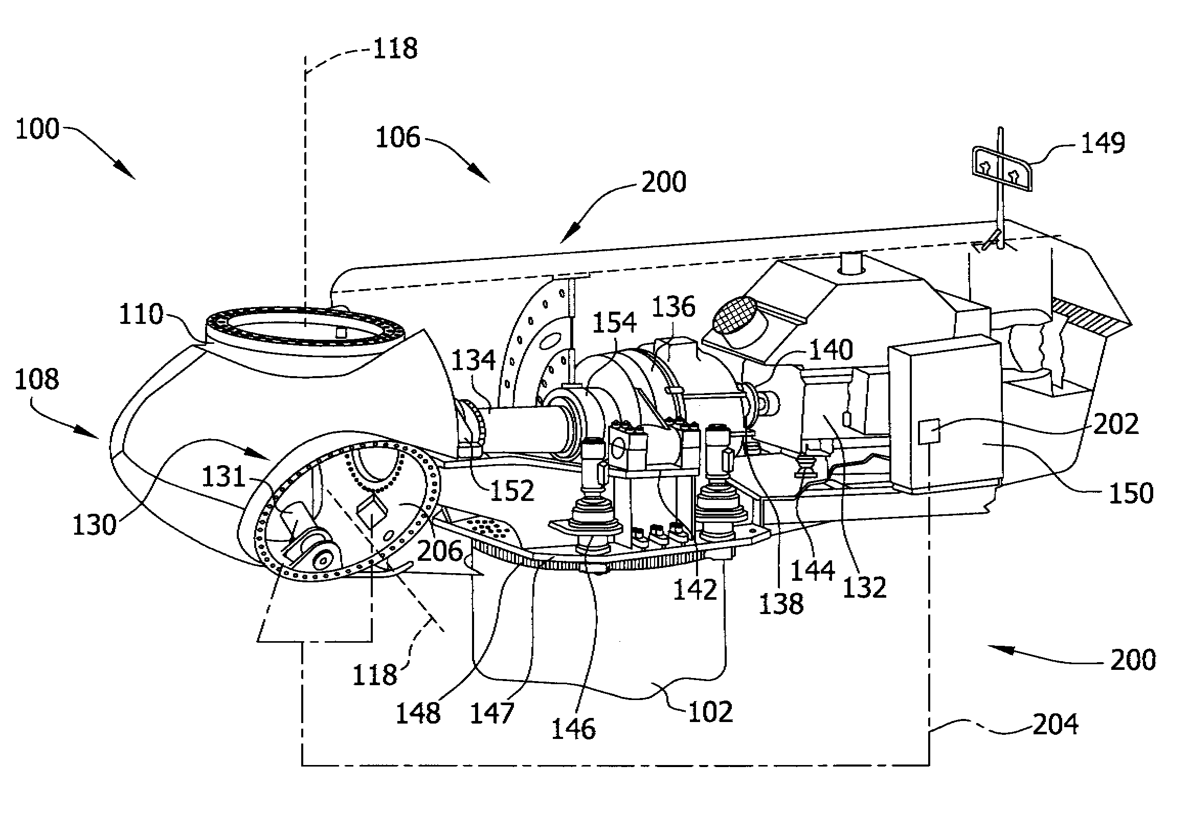
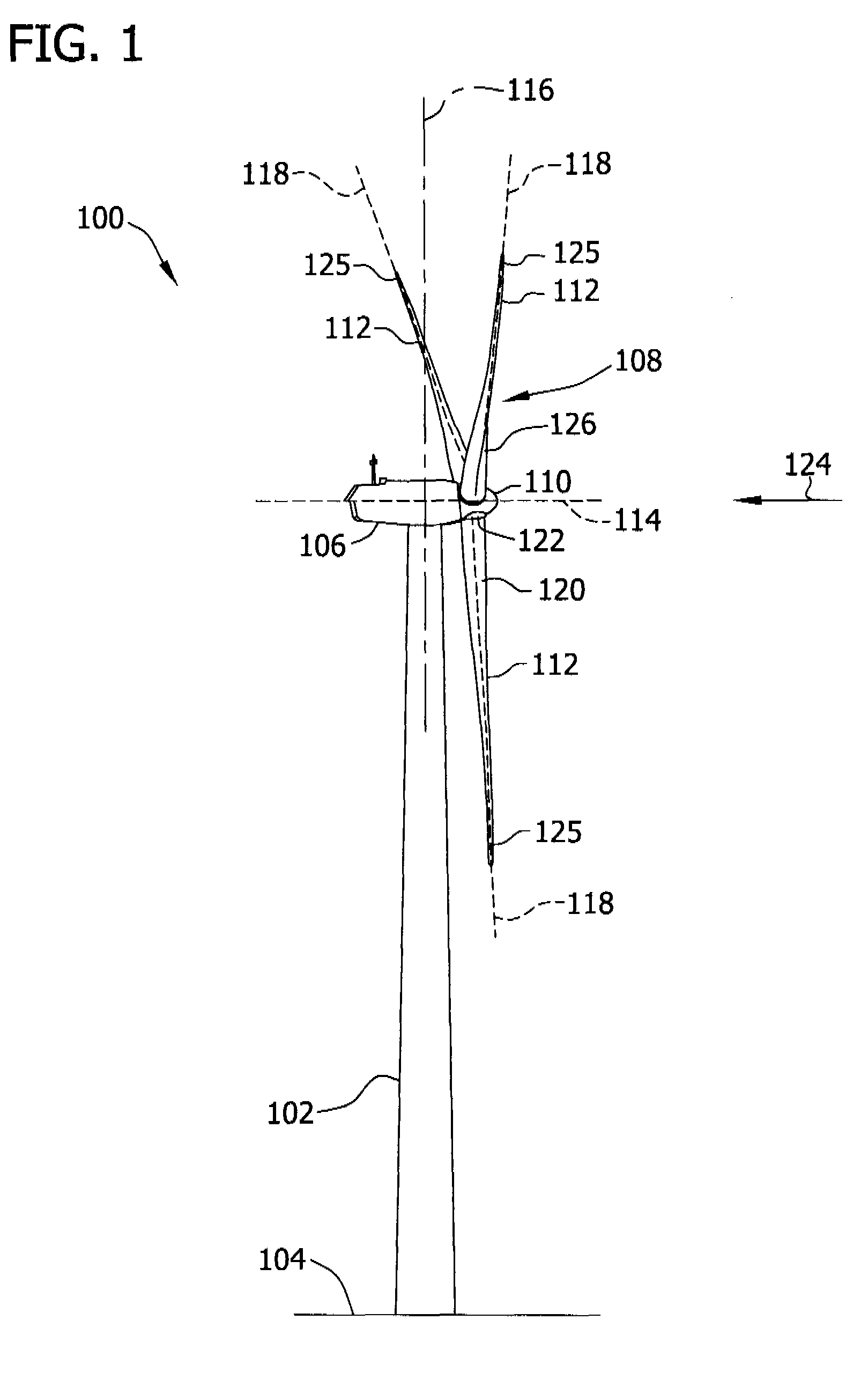
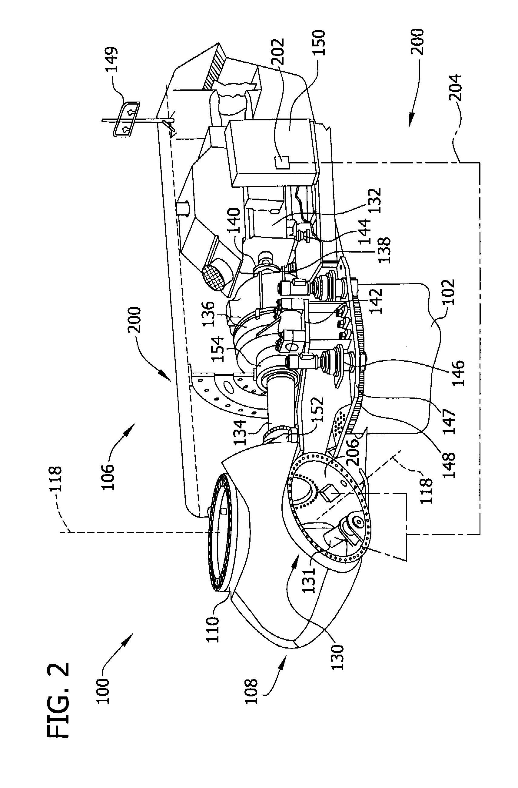
[0016]FIG. 1 is a schematic view of an exemplary wind turbine generator 100. In the exemplary embodiment, wind turbine generator 100 is a horizontal axis wind turbine. Alternatively, wind turbine generator 100 may be a vertical axis wind turbine. Wind turbine generator 100 has a tower 102 extending from a supporting surface 104, a nacelle 106 coupled to tower 102, and a rotor 108 coupled to nacelle 106. Rotor 108 has a rotatable hub 110 and a plurality of rotor blades 112 coupled to hub 110. In the exemplary embodiment, rotor 108 has three rotor blades 112. Alternatively, rotor 108 has any number of rotor blades 112 that enables wind turbine generator 100 to function as described herein. In the exemplary embodiment, tower 102 is fabricated from tubular steel and has a cavity (not shown in FIG. 1) extending between supporting surface 104 and nacelle 106. Alternatively, tower 102 is any tower that enables wind turbine generator 100 to function as described herein including, but not li...


PUM

PropertyMeasurementUnit
Forceaaaaaaaaaa
Torqueaaaaaaaaaa

Abstract

A yaw drive assembly for a rotatable system includes an input shaft configured to receive a torque from a yaw drive motor coupled within a body of the rotatable system, wherein the torque facilitates rotating the rotatable system about a yaw axis. The yaw drive assembly includes at least two output shafts configured to receive the torque and transmit a rotational yaw force to the rotatable system, and a differential gear stage operatively coupled to the two output shafts, wherein the differential gear stage includes a differential planetary gear configured to drive a pinion coupled to each of the two output shafts.

Description

BACKGROUND OF THE INVENTION[0001]The field of the disclosure relates generally to wind turbine generators and, more particularly, to control devices for use on wind turbine generators.[0002]At least some known wind turbine generators include a rotor having multiple blades. The rotor is sometimes coupled to a housing, or nacelle, that is positioned on top of a base, for example, a truss or tubular tower. At least some known utility grade wind turbines (i.e., wind turbines designed to provide electrical power to a utility grid) have rotor blades having predetermined shapes and dimensions. The rotor blades transform mechanical wind energy into induced blade lift forces that further induce a mechanical rotational torque that drives one or more generators, subsequently generating electric power. The generators are sometimes, but not always, rotationally coupled to the rotor through a gearbox. The gearbox steps up the inherently low rotational speed of the turbine rotor for the generator ...

Claims


Application Information

Patent Timeline
IPC IPC(8): F16H48/06B23P11/00
CPCF03D1/00F03D7/0204F05B2260/40311Y10T29/49826F16H37/0826Y02E10/723F05B2270/328Y02E10/72
Inventor AIYAKKANNU, NIRMAL KUMAR
Owner GENERAL ELECTRIC CO
Why Eureka
Try Eureka