
System for measuring space width of joint, method for measuring space width of joint and recording medium

a technology of space width and measurement method, which is applied in the field of system a method for measuring space width of joint and a recording medium, can solve the problems of inability to perform accurate diagnosis, conventionally very difficult to compare the positions and spaces of space width between the present and the past image, and inability to accurately diagnose. accurate diagnosis, the effect of facilitating the correlation of points

Inactive Publication Date: 2010-06-10
FUJIFILM CORP
View PDF7 Cites 29 Cited by
  • Summary
  • Abstract
  • Description
  • Claims
  • Application Information

AI Technical Summary

Benefits of technology

[0019]Further, it is an object of the presently disclosed subject matter to provide a joint space width measuring system, a method for measuring space width of joint and a program which bring related places into correspondence with each other in a plurality of images and display the images with a space width and the like, and can perform useful diagnosis of a hip joint disease including the advance extent of the disease.
[0023]Thereby, the contour is detected by interpolating a plurality of points on the contour which are inputted by the information input unit. Therefore, the burden on the user is reduced, and an accurate contour can be detected.
[0025]Thereby, the contour is detected based on a plurality of edge points in the edge image of the joint, and therefore, a more accurate contour can be detected.
[0053]Thereby, the user can easily confirm where the position which the minimum space width is measured in the previous measurement time is located this time (present measurement time), or where the position which the minimum space width is measured this time is located at the previous time. The aspect is very useful for comparison in diagnosis.
[0056]Thereby, the user can easily confirm correspondence of the point on the image of the joint or the contour image, and the point on the space width graph, and can also perform effective diagnosis for the disease of the joint.

Problems solved by technology

Thus, when a user manually inputs the above described positional information as described in the above described Japanese Patent Application Laid-Open No. 2007-151742, the position of the thigh femoral head center or the like varies each time, depending on the user who inputs the information, the timing of measurement and the like, and accurate diagnosis cannot be performed.
Further, in the diagnosis of a hip joint disease, for example, the measurement position of the minimum space width may differ at present and in the past depending on the advance extent of the disease and treatment, and therefore, there is the problem of being unable to perform accurate diagnosis only by simply comparing the minimum value of the space width numerically.
However, due to advanced diseases and the other causes, it has been conventionally very difficult to compare the positions and spaces of the space widths quantitatively between the present and the past images.
The techniques described in the prior art documents such as Japanese Patent Application Laid-Open No. 9-56706, Japanese Patent Application Laid-Open No. 9-18685, Japanese Patent Application Laid-Open No. 2004-275361 and Japanese Patent Application Laid-Open No. 2002-203248 are useful techniques when sequential comparison is performed in image diagnosis, but are unable to perform comparison of the joint space widths as described above or display of the related portions.
Further, in the above described prior art documents, when the serial data of the measured space width are displayed by being compared between the past and present, and a plurality of images of the past, present and the like are displayed, the positions and the values of the space widths are not displayed by bringing the related places into correspondence with each other on the respective images, and the line images are only displayed by being superimposed on medical images, thereby causing the problem that advance extent of the disease cannot be diagnosed, and useful diagnosis of a hip joint disease cannot be performed.

Method used


Image

  • System for measuring space width of joint, method for measuring space width of joint and recording medium
  • System for measuring space width of joint, method for measuring space width of joint and recording medium
  • System for measuring space width of joint, method for measuring space width of joint and recording medium

Examples


Embodiment Construction

[0106]Hereinafter, a system for measuring space width of joint, a method for measuring space width of joint and a program according to the presently disclosed subject matter will be described in detail with reference to the attached drawings.

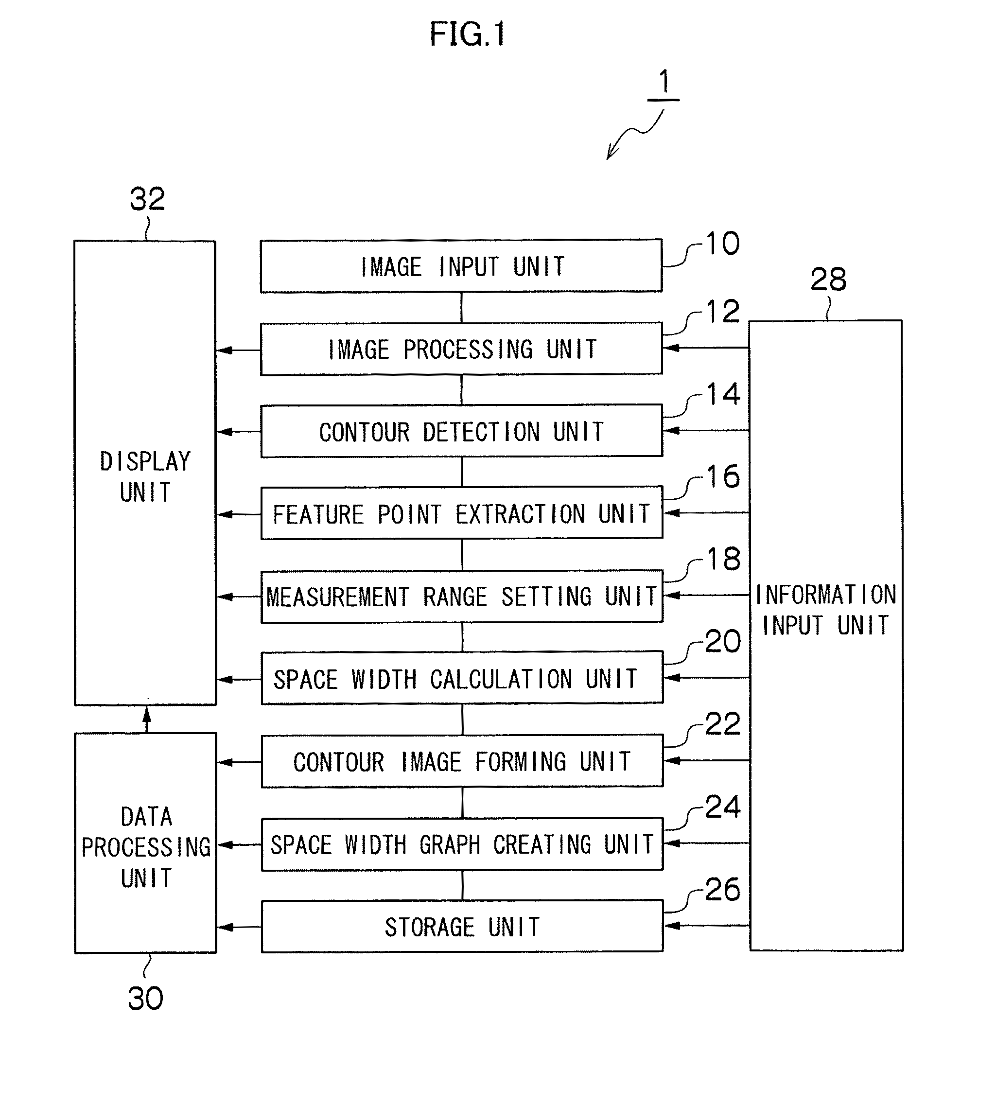
[0107]FIG. 1 is a block diagram showing a schematic configuration of one embodiment of the system for measuring space width of joint according to the presently disclosed subject matter.

[0108]As shown in FIG. 1, a system 1 for measuring space width of joint of the present embodiment includes an image input unit 10, an image processing unit 12, a contour detection unit 14, a feature point extraction unit 16, a measurement range setting unit 18, a space width calculation unit 20, a contour image forming unit 22, a space width graph creating unit 24, a storage unit 26, an information input unit 28, a data processing unit 30 and a display unit 32.

[0109]The image input unit 10 receives X-ray image data obtained by radiographing an examined region of a...


PUM


Abstract

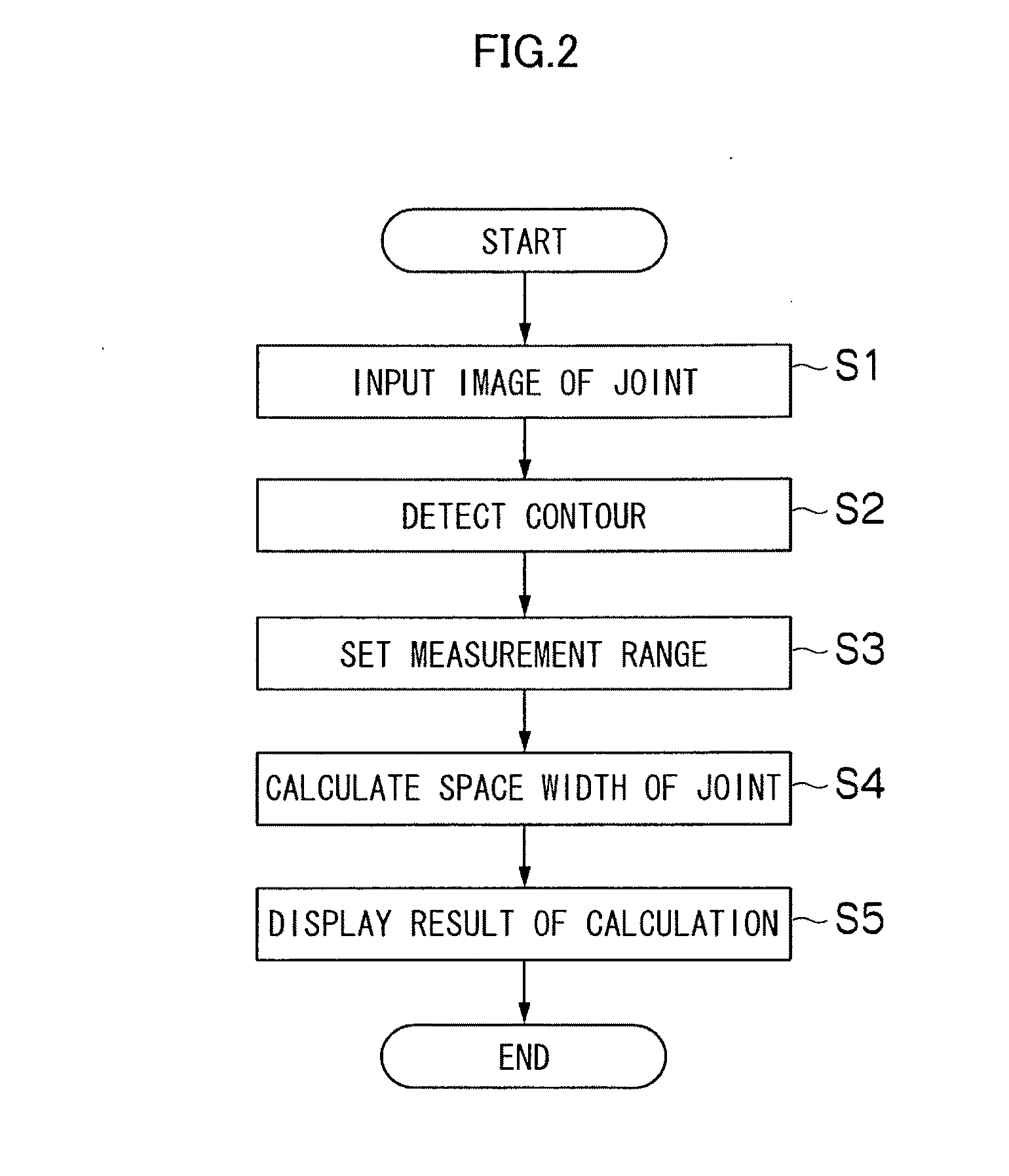
A method for measuring space width of joint includes: a joint image input step of inputting an image of a joint; a contour detecting step of detecting contours of a pair of bones constituting the joint; a measurement range setting step of setting a measurement range of a space of the joint based on the contours detected in the contour detecting step; a space width calculating step of calculating a space width which is a distance between the pair of bones within the measurement range set in the measurement range setting step; and a display step of displaying the space width calculated in the space width calculating step.

Description

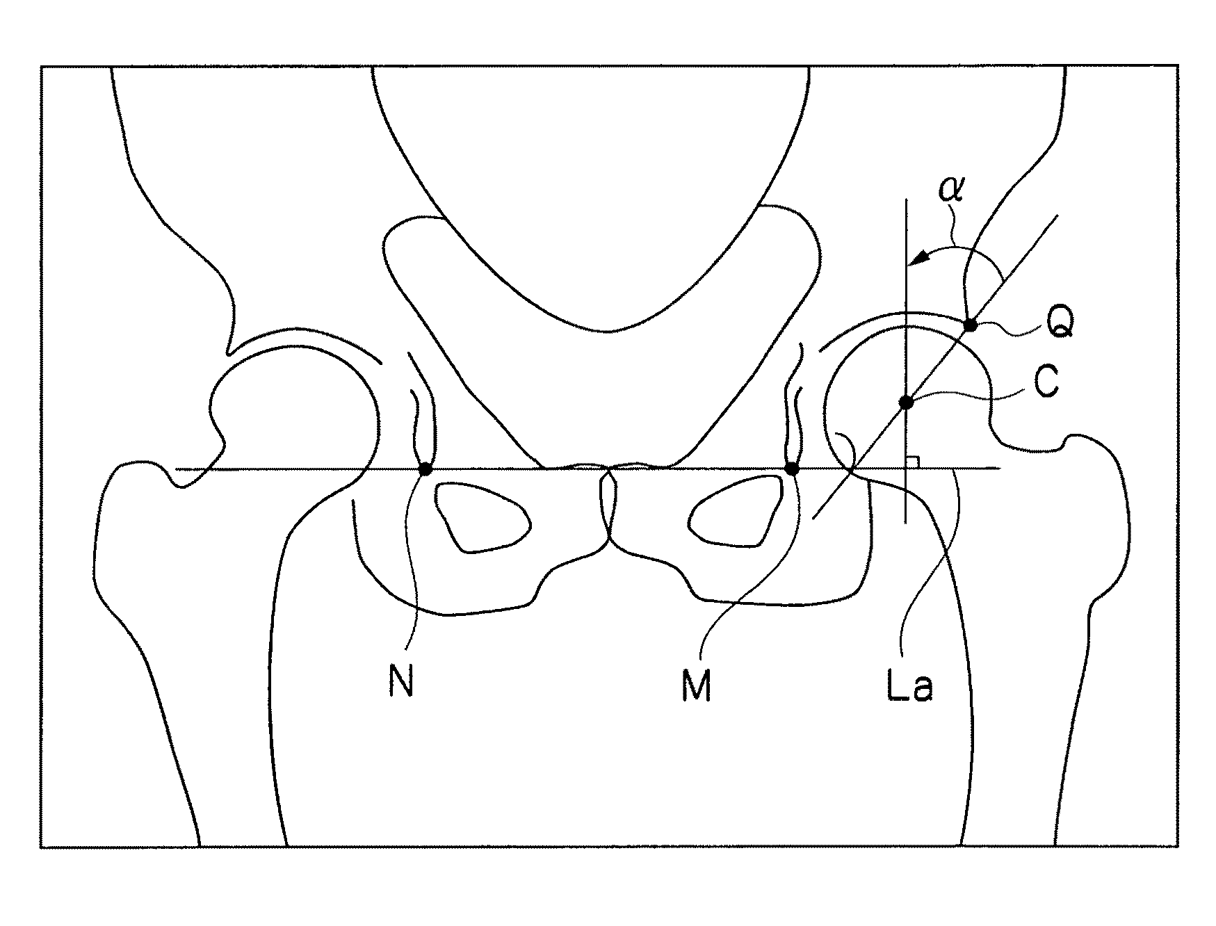
CROSS-REFERENCE TO RELATED APPLICATIONS[0001]This application claims the priority benefit under 35 U.S.C. §119 of Japanese Patent Application No. 2008-310122 filed on Dec. 4, 2008, Japanese Patent Application No. 2008-310128 filed on Dec. 4, 2008, Japanese Patent Application No. 2009-87492 filed on Mar. 31, 2009 and Japanese Patent Application No. 2009-87844 filed on Mar. 31, 2009, which are hereby incorporated in its entirety by reference.BACKGROUND OF THE INVENTION[0002]1. Field of the Invention[0003]The presently disclosed subject matter relates to a system for measuring space width of joint, a method for measuring space width of joint and a recording medium, and particularly relates to the technique of aiding measurement in orthopedic surgery by detecting an anatomical feature point of a human body structure such as a center of a thigh femoral head, and measuring a space width of a joint of a hip joint and comparing images photographed at different times to make the images avail...

Claims


Application Information

Patent Timeline
Patent Type & Authority Applications(United States)
IPC IPC(8): A61B5/103
CPCA61B5/1075A61B5/4528A61B6/00G06T7/0012G06T2207/30008G06T7/60G06T2207/10116G06T2207/20096G06T7/0083G06T7/12
Inventor TAKAHASHI, TOMOYUKIIDA, NORIAKI
Owner FUJIFILM CORP
Learn More