Instrumented orthopaedic implant for identifying a landmark

a landmark and instrumentation technology, applied in the field of orthopaedic implants, can solve the problems of incorrect entry point of bone, distal locking, inaccurate jig for distal screws,

Active Publication Date: 2010-06-10
SMITH & NEPHEW INC
View PDF98 Cites 62 Cited by
  • Summary
  • Abstract
  • Description
  • Claims
  • Application Information

AI Technical Summary

Benefits of technology

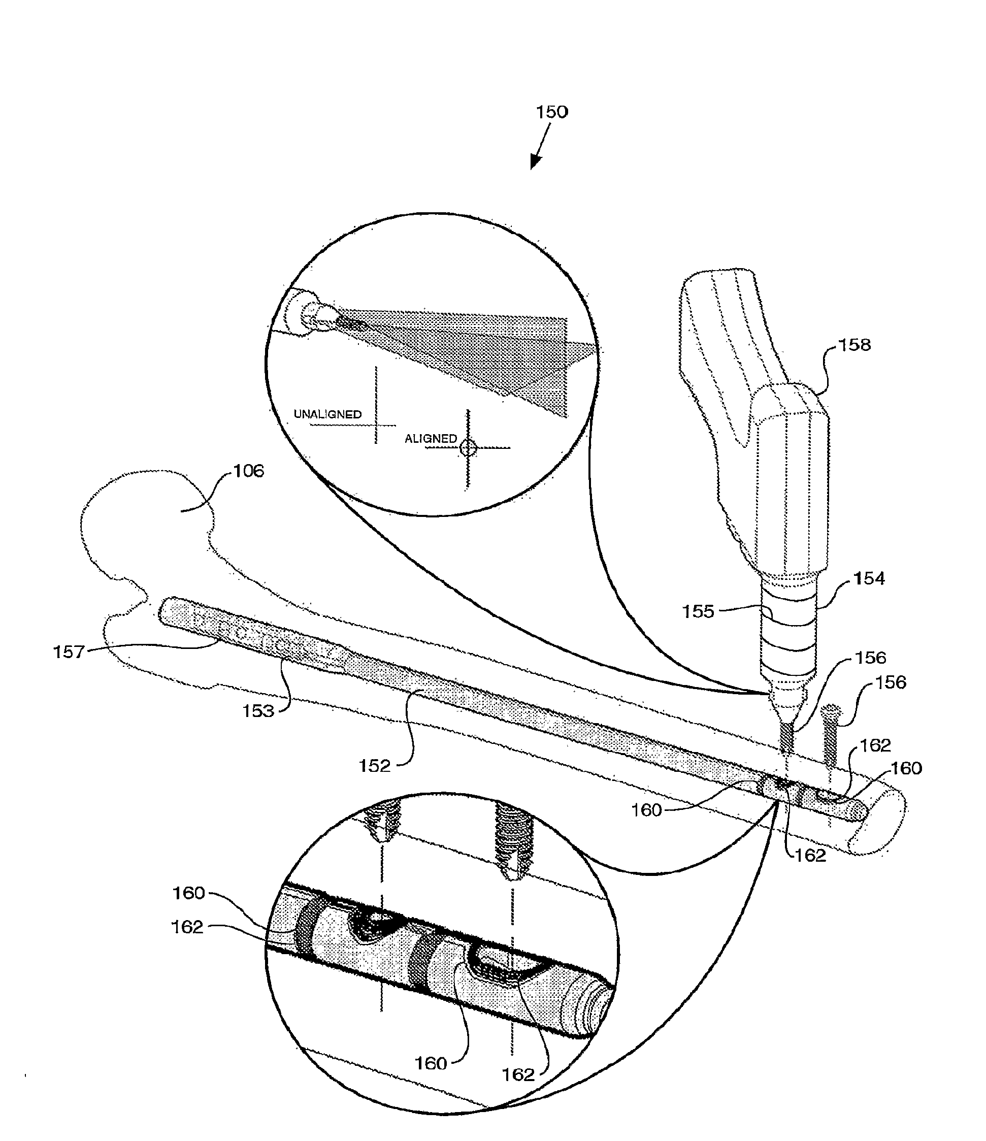
[0021]In yet another aspect of the invention, there is provided a method of targeting a landmark relative to an instrumented orthopaedic implant. The method includes the steps of: (a) installing an instrumented orthopaedic implant relative to a bone, the instrumented orthopaedic implant having at least one landmark and at least one corresponding coil proximate to the at least one landmark; (b) energizing the at least one corresponding coil; (c) orienting a landmark identifier relative to the energized at least one corresponding coil; (d) sensing the energized at least one corresponding coil; (e) processing the sensed at least one corresponding coil data to detect proximity of the landmark identifier relative to the energized at least one corresponding coil; and (f) providing a user with feedback information on the proximity of the landmark identifier relative to the energized at least one corresponding coil.

Problems solved by technology

Nail deformation during intramedullary insertion, however, may make a jig inaccurate for the distal screws.
The primary difficulty lies in the positioning of the distal locking screws and alignment of the drill for the drilling of the distal screw holes because it is the most time consuming and challenging step of the overall implantation procedure.
Consequently, the two main reasons for failure in distal locking are incorrect entry point on the bone and wrong orientation of the drill.
An inaccurate entry point also compounds the problem as the rounded end of the drill bit often slips, and it is then difficult to place another drill hole next to the earlier one.
Inaccurate distal locking leads to premature failure with breakage of the nail through the nail hole, breakage of the screw or the breaking of the drill bit within the bone.

Method used


Image

  • Instrumented orthopaedic implant for identifying a landmark
  • Instrumented orthopaedic implant for identifying a landmark
  • Instrumented orthopaedic implant for identifying a landmark

Examples


Embodiment Construction

[0063]The following description of the preferred embodiment(s) is merely exemplary in nature and is in no way intended to limit the invention, its application, or uses.

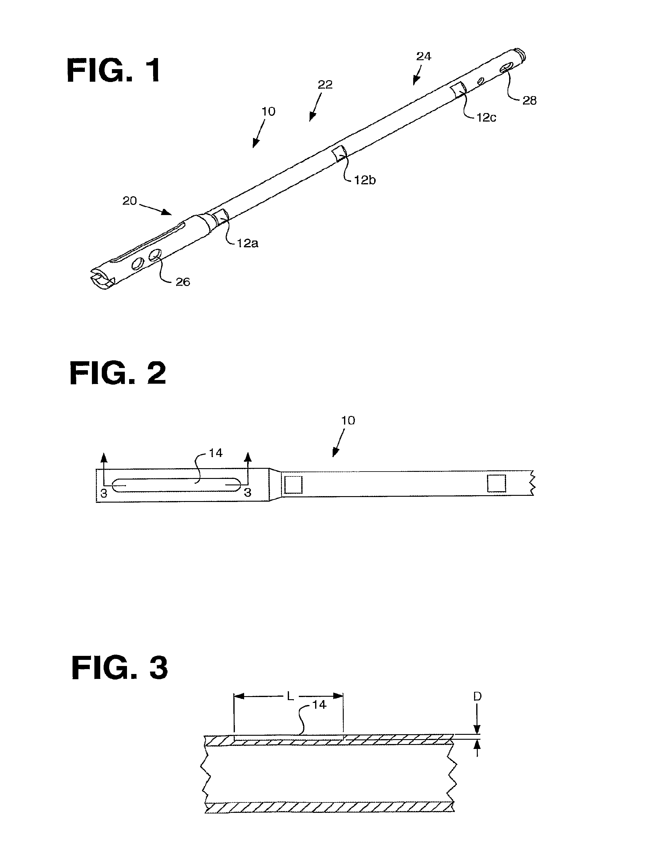
[0064]A “smart implant” is an implant that is able to sense its environment, apply intelligence to determine whether action is required, and act on the sensed information to change something in a controlled, beneficial manner. One attractive application of smart implant technology is to measure loads on an orthopaedic implant. For example, an intramedullary nail is subjected to three types of loading: bending, torsional, and compression. These loads may be measured indirectly by measuring sensor output of a series of strain gauges mounted to the orthopaedic implant. In the case of an intramedullary nail, diametrically apposed strain gauges mounted on the outer surfaces of the nail are subjected to tensile and compressive forces, respectively. Typically, the strain measured from the sensors is higher when the implant i...


PUM


Abstract

A system (110, 150) for targeting a landmark (114, 160) is disclosed. The system includes an instrumented medical implant (112, 152), a control circuit (118, 153), a power supply (120, 157), and a landmark identifier (122, 154). The instrumented medical implant (112, 152) has one or more landmarks (114, 160) and each landmark (114, 160) has a corresponding coil (116, 162). The control circuit (118, 153) is electrically connected to the corresponding coil (116, 162), and the power supply (120, 157) is electrically connected to the control circuit (118,153). The landmark identifier (122, 154) has a magnetic sensor (124, 155) for sensing the corresponding coil (116, 162).

Description

CROSS-REFERENCE TO RELATED APPLICATIONS[0001]N / ABACKGROUND OF THE INVENTION[0002]1. Field of the Invention[0003]The present invention relates generally to orthopaedic implants and more particularly to an instrumented orthopaedic implant for identifying a landmark.[0004]2. Related Art[0005]The interlocking femoral nail has significantly widened the scope for intramedullary (IM) fixation of long bone fractures. Locking an IM nail makes the construct more stable longitudinally and stops rotation of the nail within the bone. A typical IM nail fixation surgery involves a combination of jigs, x-ray imaging, and manual eye-balling to locate and drill the distal screw holes.[0006]In this surgical procedure, an IM nail is hammered into the canal of a fractured long bone in order to fixate the fractured ends together. The proximal locking is performed first and is usually carried out with a jig. Nail deformation during intramedullary insertion, however, may make a jig inaccurate for the dista...

Claims


Application Information

Patent Timeline
Patent Type & Authority Applications(United States)
IPC IPC(8): A61B17/56
CPCA61B17/1707A61B17/1725A61B19/5244A61B2019/547A61B17/72A61B2090/397A61B34/20
Inventor JANNA, SIED W.WILSON, DARREN JAMESMORGAN, ROBERT L.
Owner SMITH & NEPHEW INC
Why Eureka
Try Eureka