Industrial robot and method to operate an industrial robot

Inactive Publication Date: 2010-06-10
KUKA LAB GMBH
View PDF12 Cites 16 Cited by
  • Summary
  • Abstract
  • Description
  • Claims
  • Application Information

AI Technical Summary

Benefits of technology

[0010]An object of the present invention is to provide a cost-effective, reliable and (

Problems solved by technology

Resolvers possess a relatively limited resolution, however, and have relatively large angle errors, typically in the range of a few angular minutes.
In contrast to resolvers, rotary encoders are considered u

Method used


Image

  • Industrial robot and method to operate an industrial robot
  • Industrial robot and method to operate an industrial robot
  • Industrial robot and method to operate an industrial robot

Examples


Embodiment Construction

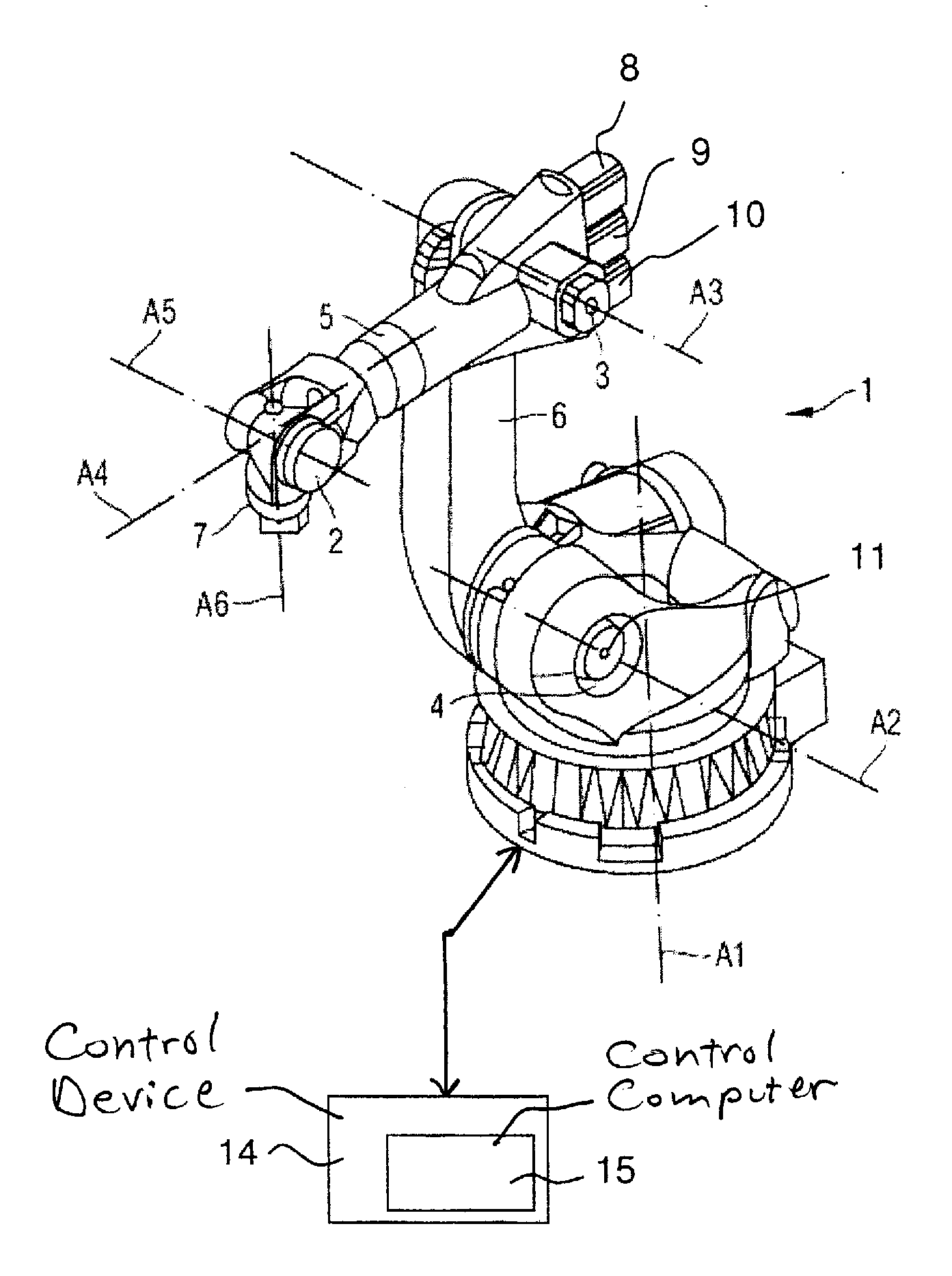
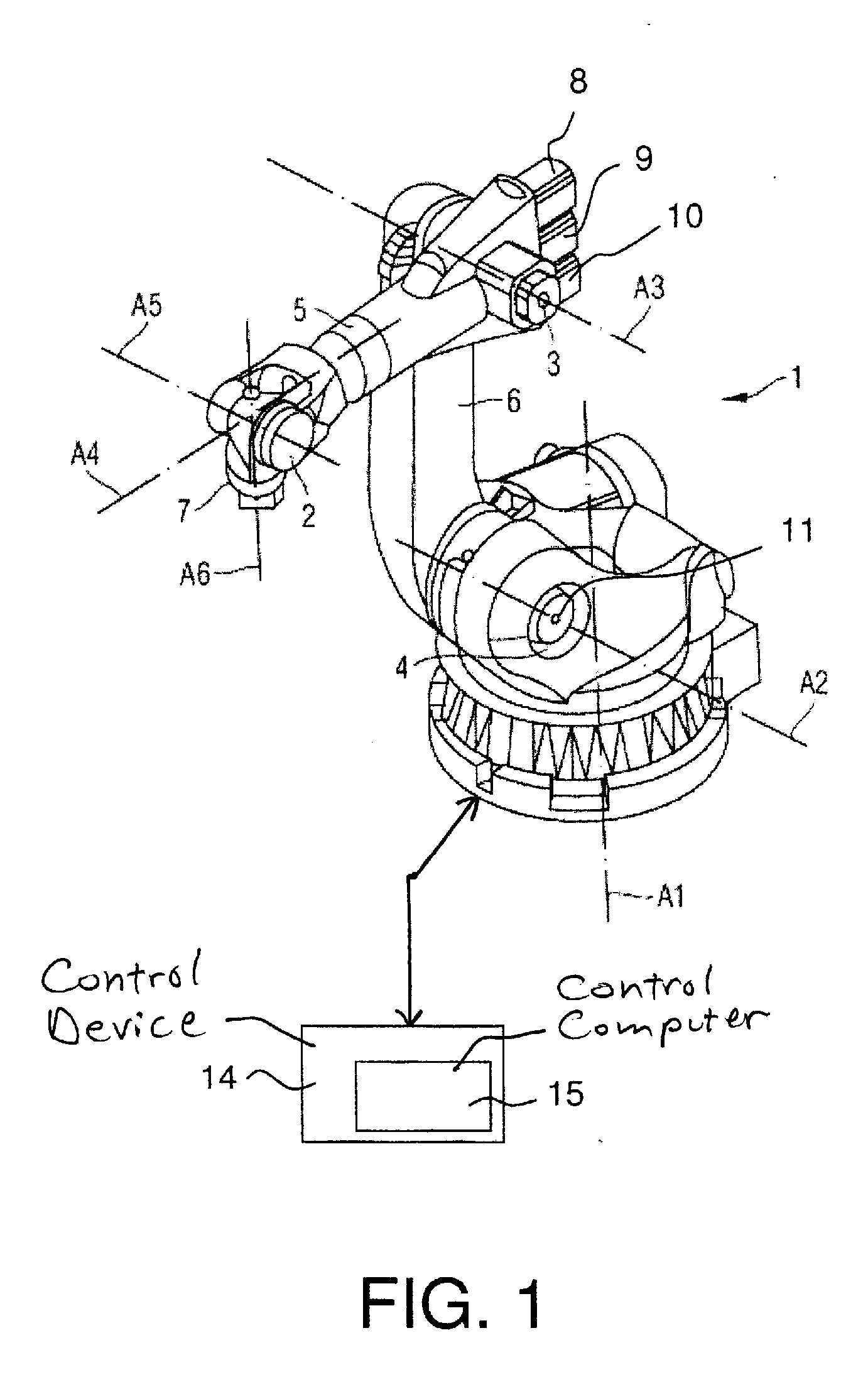
[0035]FIG. 1 shows an industrial robot 1 with kinematics for movements in six degrees of freedom. The industrial robot 1 has in a generally known manner, joints 2 through 5, arm 6, six movement axes A1 through A6 and a flange 7.

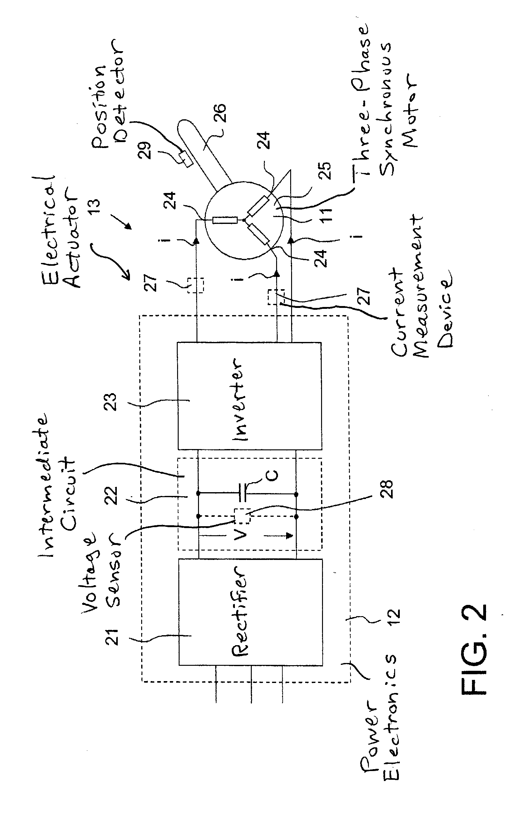
[0036]Each of the axes A1-A6 is moved by an drive 13, all of which, in the case of the present exemplary embodiment, are electrical drives and each has a motor 8-11. For example, the motor 11 or the corresponding electrical drive 13 that is shown in FIG. 2 moves the axis A2, possibly by means of a transmission gearbox (not shown in detail but generally known to those skilled in the art).

[0037]In the exemplary embodiment, the electrical motors 8-11 are three-phase synchronous motors, in particular permanently energized synchronous motors. The motors 8-11 are each activated by power electronics 12 (what are known as converters) that, in the exemplary embodiment, are arranged in a control device 14. Each power electronics 12 is electrically connected with one of...


PUM


Abstract

In an industrial robot and a method for operating an industrial robot, a robot arm is pivotable with respect to multiple axes. At least one of the axes has an drive associated therewith for controlling movement of the robot arm with respect to that axis. The electrical drive includes a three-phase synchronous motor that is operated with associated electrical currents and electrical voltages. A signal representing at least one of said electrical currents and electrical voltages is supplied to a computerized control unit that determines, from the signal, the position of the axis associated with the electrical drive. The computerized control unit controls operation of the electrical drive dependent on this determined position.

Description

BACKGROUND OF THE INVENTION[0001]1. Field of the Invention[0002]The present invention concerns an industrial robot and a method to operate an industrial robot.[0003]2. Description of the Prior Art[0004]Industrial robots are manipulation machines that are equipped for automatic manipulation of objects with appropriate tools and can be programmed in multiple movement axes, in particular with regard to orientation, position and workflow. Industrial robots essentially have a robot arm with multiple axes and arms that are moved by drives. The drives are, for example, electrical drives that can be operated by synchronous motors.[0005]For the operation of the industrial robot, it is necessary to register the positions of the movement axes, for example their angle positions, in particular in a reliable technique.[0006]For a reliable position detection, in particular of position-controlled electrical drives, the position (in particular the angle position of the rotor of the electrical motor ...

Claims


Application Information

Patent Timeline
IPC IPC(8): G05B15/00H02P6/16
CPCB25J9/1674B25J9/1694G05B2219/42329G05B2219/37317G05B2219/42318G05B19/4062
Inventor KEYL, HARTMUTNITZ, GERNOT
Owner KUKA LAB GMBH
Why Eureka
Try Eureka