Small engine operation components

a technology for internal combustion engines and operation components, applied in the direction of electric control, muscle operated starters, instruments, etc., can solve the problems of difficult to adjust for maximum efficiency, high maintenance costs of carburetor based systems, and unsatisfactory levels of emissions, so as to achieve quick adjustment of fuel duration

Active Publication Date: 2010-06-10
PCRC PRODS
View PDF14 Cites 35 Cited by
  • Summary
  • Abstract
  • Description
  • Claims
  • Application Information

AI Technical Summary

Benefits of technology

[0013]Another feature of the disclosure is an adaptive algorithm relying primarily on rotational speed which quickly adjusts fuel duration provided to the engine so that engine speed quickly adjusts to conditions of use. A particular feature of the preferred embodiment is a use of a smart choke algorithm which adjusts timing in accordance with predetermined conditions.

Problems solved by technology

However, such carburetor based systems are relatively fuel inefficient, resulting in undesirable levels of emissions caused by engine operations that generate excessive hydrocarbons and evaporative emissions.
Additionally, carburetor based systems usually require high maintenance and are difficult to adjust for maximum efficiency.
Carburetor based systems also can be hard to start in certain conditions and are difficult to operate in normal use.
The starting problem is particularly evident with small two cycle engines employed with edgers and blowers, for example, whose overall designs, normally of a rope pull nature, make starting the engines difficult, even when the fuel systems are fully functional.
In addition, the application of the technology to relatively low cost hand-held implements has heretofore been hindered by the excessive costs associated with the fuel systems.
This complexity has resulted in substantial cost, and merely adopting or scaling prior art solutions to the problem has not resulted in commercially viable systems for smaller applications.
As indicated, the '596 patent works well for its intended purpose, but is not adaptable to low cost, small gasoline engines to which the present disclosure applies.
While the '596 patent includes a microprocessor, a thermocouple, exhaust gas temperature sensor, and a fuel regulating valve installed in a low-pressure fuel delivery system between the fuel tank and the carburetor, the application of that technology to smaller engines is cost prohibitive in the form described in the '596 patent.

Method used


Image

  • Small engine operation components
  • Small engine operation components
  • Small engine operation components

Examples


Embodiment Construction

[0054]The following detailed description illustrates the present disclosure by way of example and not by way of limitation. It should be understood that various aspects of the disclosure may be implemented individually or in combination with one another. The description clearly enables one skilled in the art to make and use the development which we believe to be new and unobvious, describes several embodiments, adaptations, variations, alternatives, and uses of the system, including what is presently believed to be the best mode of carrying out the inventive principles described in this specification. When describing elements or features and / or embodiments thereof, the articles “a”, “an”, “the”, and “said” are intended to mean that there are one or more of the elements or features. The terms “comprising”, “including”, and “having” are intended to be inclusive and mean that there may be additional elements or features beyond those specifically described.

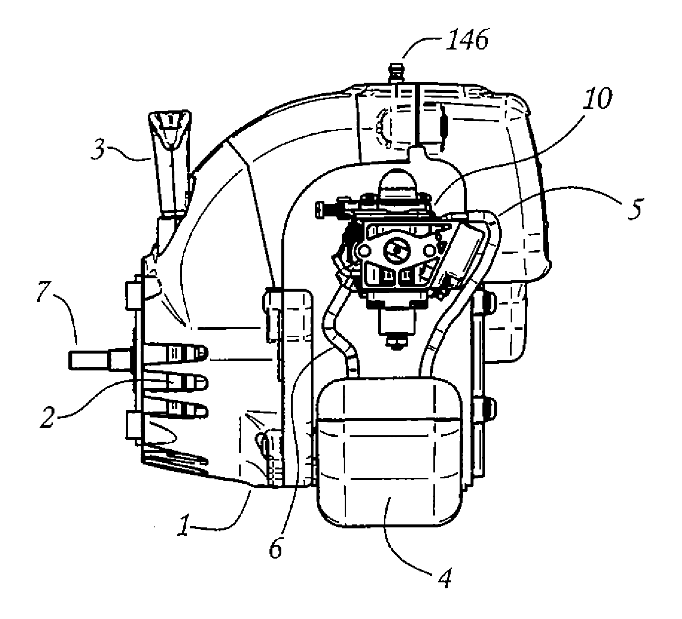
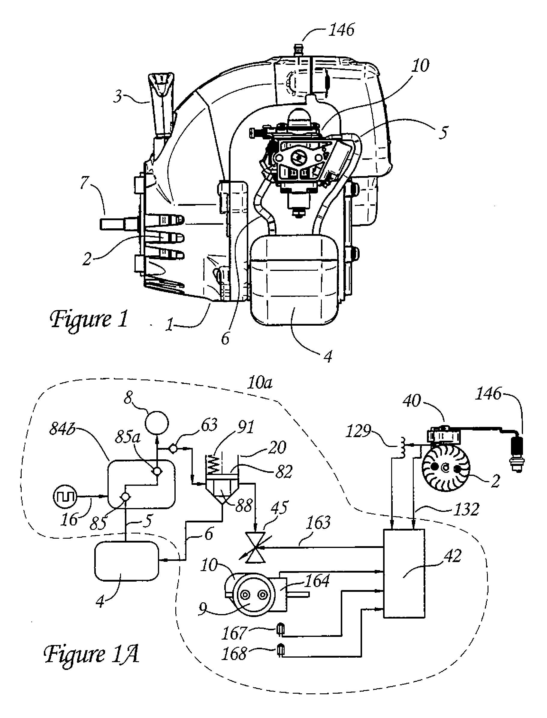
[0055]Referring to FIG. 1, ref...


PUM


Abstract

A low pressure, low cost electronic fuel injection system (18) for small hand-held two cycle engines (1) is provided which employs a number of improvements, including by way of example and not of limitation, an improved low cost injector construction (45), a throttle body integration (10) that includes mounting the operational components of the supply system on a single unit, an improved ignition module (40), a pressure regulated fuel system controlled by an electronic control unit (42) employing and an adaptive algorithm based on engine speed which controls the speed by varying the amount of fuel provided to the engine.

Description

RELATED APPLICATIONS[0001]This application claims priority to U.S. Provisional Application Ser. No. 60 / 834,592, filed Aug. 1, 2006, the specification of which is incorporated herein by reference.STATEMENT REGARDING COPYRIGHT[0002]A portion of the disclosure of this patent document contains material which is subject to copyright protection. The copyright owner has no objection to the facsimile reproduction by anyone of the patent document or the patent disclosure, as it appears in the Patent and Trademark Office patent file or records, but otherwise reserves all copyright rights whatsoever.BACKGROUND ART[0003]This invention relates generally to an electronic fuel regulation system, and more particular, to an electronic fuel regulation system for small internal combustion engines, which in the preferred embodiment are hand-held garden implements utilizing a conventional two-cycle engine design. The invention may also be used in other small internal combustion engines and in other appl...

Claims


Application Information

Patent Timeline
Patent Type & Authority Applications(United States)
IPC IPC(8): F02D41/30F02N1/00F02D41/06
CPCF02B75/34F02M55/007F02D31/007F02D41/009F02D41/062F02D41/3005F02D2009/0232F02D2400/06F02D2400/18F02M51/0635F02M61/14F02M69/02F02M69/044F02M69/462F02M69/54F02N3/02F02M49/00F02D11/10Y02T10/12
Inventor BELLISTRI, JAMES T.HAJJI, MAZEN J.MAVINAHALLY, NAGESH S.BROWER, DAVID R.
Owner PCRC PRODS
Why Eureka
Try Eureka