
Imaging device

a technology of imaging device and dust removal, which is applied in the direction of carpet cleaners, instruments, and exposure control, etc., can solve the problems of easy entry of dust into the camera, deposition of dust on the imaging device relatively often, and the quality of the captured image is affected, so as to prevent the redeposition of dust, reduce the effect of dust removal efficiency and prevent the effect of dust redeposition

Inactive Publication Date: 2010-06-17
SONY CORP
View PDF1 Cites 6 Cited by
  • Summary
  • Abstract
  • Description
  • Claims
  • Application Information

AI Technical Summary

Benefits of technology

[0012]According to the invention of Claim 4, in the imaging apparatus according to the invention of any one of Claims 1 to 3, the control means allows the imaging device to be vibrated after the completion of exposure of an image shot by the imaging device to remove dust deposited on the imaging device.
[0021]Particularly, according to the invention disclosed in Claim 5, since the imaging device is vibrated so long as it is determined that the photographic lens is not mounted and the opening for lens mounting is pointed down, dust deposited on the imaging device can be more reliably discharged from the imaging apparatus. Advantageously, redeposition of dust on the imaging device can be prevented, thus allowing for efficient dust removal.

Problems solved by technology

In a digital camera which serves as an imaging apparatus for capturing an image using an imaging device, such as a CCD, deposition of dust, such as fine particles of a substance or dirt, on the imaging device causes a degradation in quality of the captured image.
Particularly, in a lens interchangeable digital camera, dust easily enters the camera during change of a lens.
Disadvantageously, deposition of dust on an imaging device relatively often occurs.
In the above-described technique disclosed in Japanese Unexamined Patent Application Publication No. 2005-159711, unfortunately, dust temporarily removed from the imaging device by vibration may be again deposited on the imaging device according to circumstances when the vibration is applied to the imaging device.

Method used


Image

  • Imaging device
  • Imaging device
  • Imaging device

Examples


first embodiment

1. First Embodiment

1-1. Structure

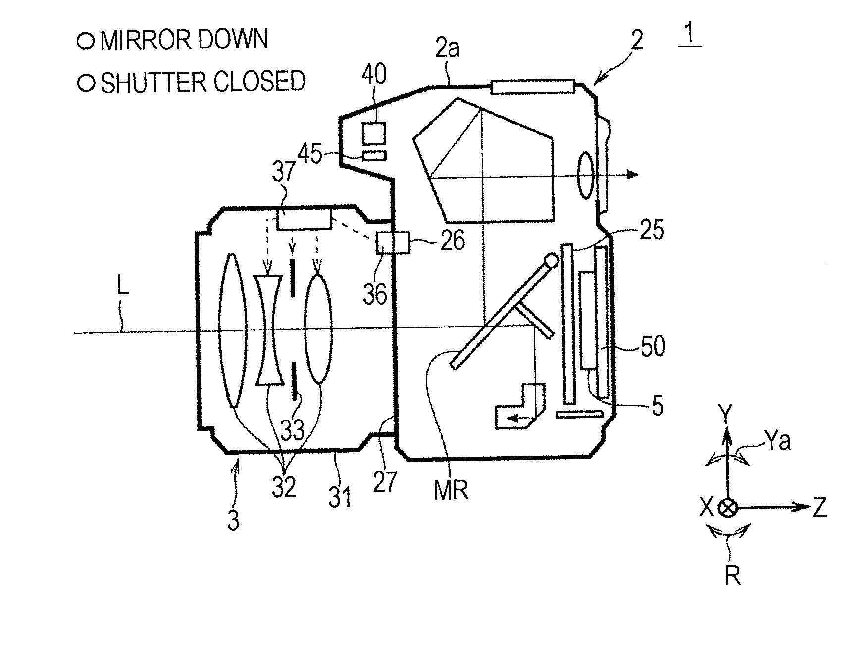
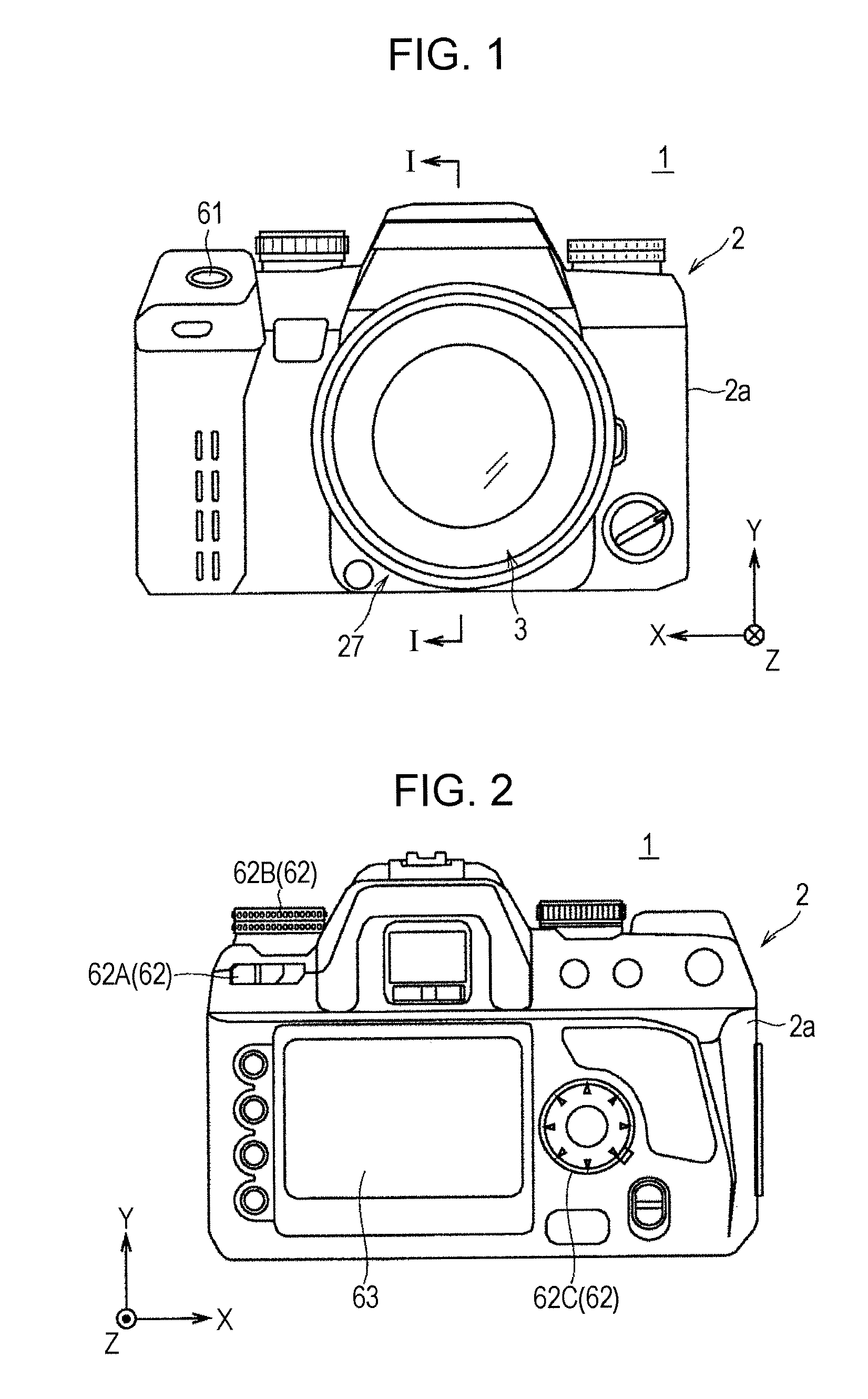
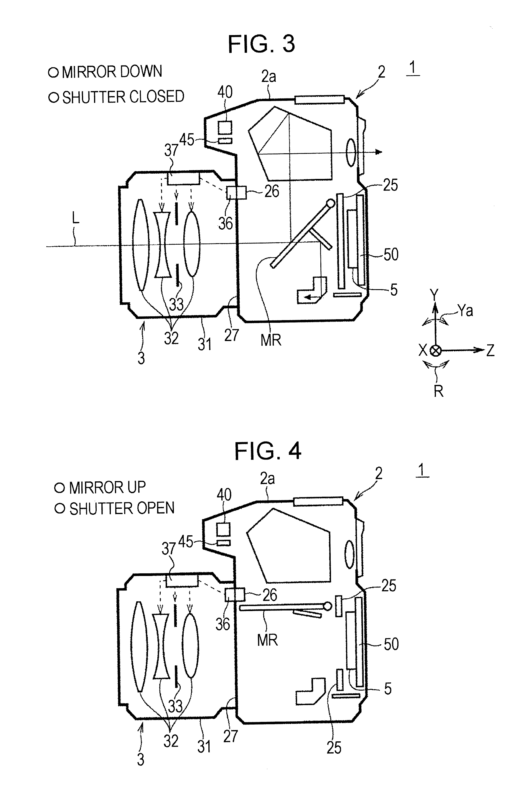
[0040]FIG. 1 is a front elevation of a digital camera 1 (also indicated at 1A), serving as an imaging apparatus, according to a first embodiment of the present invention. FIG. 2 is a rear elevation of the digital camera 1. FIGS. 3 and 4 are cross-sectional views (specifically, cross-sectional views taken along the line I-I of FIG. 1) of the digital camera 1. FIG. 3 shows a state in which a quick return mirror (hereinafter, also simply referred to as a mirror) MR is located in a lower position (mirror down state). FIG. 4 shows a state in which the mirror MR is located in an upper position (mirror up state).

[0041]The digital camera 1 has a blur correction function of correcting (suppressing) blurring of a subject image in an image caused by camera shake during shooting and a dust removal function of removing dust (contaminant), such as fine particles of a substance or dirt, deposited on an imaging device for image capture by vibration.

[0042]Referring t...

second embodiment

2. Second Embodiment

[0084]The above-described first embodiment has described the case where when it is determined in the dust removal mode that the photographic lens is not mounted and the digital camera 1 (more specifically, the lens mount 27 or the lens mounting opening LP) is pointed down, the CCD 5 is vibrated to remove contaminant thereon. A second embodiment will exemplify a case where when it is determined in the dust removal mode that the digital camera 1 has a “normal posture” (which will be described below), the CCD 5 is vibrated to remove contaminant thereon.

[0085]A digital camera 1 (1B) according to the second embodiment is a modification of the digital camera 1 (1A) according to the first embodiment. The difference therebetween will be mainly described below.

[0086]FIG. 10 is a flowchart showing the operation in a dust removal mode in accordance with the second embodiment. FIGS. 11 and 12 are diagrams explaining the “normal posture”. FIG. 11 includes diagrams illustratin...

third embodiment

3. Third Embodiment

[0101]The foregoing first and second embodiments have described the case where the CCD 5 is vibrated in the “dust removal mode” to remove contaminant thereon. A third embodiment will exemplify a case where the CCD 5 is vibrated in the “shooting mode” to remove contaminant thereon.

[0102]A digital camera 1 (1C) according to the third embodiment is a modification of the digital camera 1 (1B) according to the second embodiment. The difference therebetween will now be mainly described.

[0103]FIGS. 13 and 14 show a flowchart showing the operation in a “shooting mode” of the digital camera 1C according to the third embodiment. The operation in the “shooting mode” will now be described with reference to FIGS. 13 and 14.

[0104]When the digital camera 1C is set to the “shooting mode”, the digital camera 1C is switched into a shooting standby state for an operation on a shutter release 61. Specifically, capturing a live view image is started (step SP51) and blur correction is ...


PUM


Abstract

An imaging apparatus capable of preventing redeposition of dust on an imaging device to efficiently achieve dust removal. The imaging apparatus includes a driving device vibrating the imaging device, a posture detecting device detecting a posture of the imaging apparatus, and a controller allowing the imaging device to be vibrated on the condition that the detected posture of the imaging apparatus is a predetermined posture to remove dust deposited on the imaging device. For example, the imaging device is vibrated on the condition that the posture of the imaging apparatus is a normal posture. Alternatively, the imaging device is vibrated so long as it is determined that an opening for lens mounting in a body of the apparatus is pointed down and a photographic lens is not mounted.

Description

TECHNICAL FIELD[0001]The present invention relates to imaging apparatuses, such as digital cameras.BACKGROUND ART[0002]In a digital camera which serves as an imaging apparatus for capturing an image using an imaging device, such as a CCD, deposition of dust, such as fine particles of a substance or dirt, on the imaging device causes a degradation in quality of the captured image. Particularly, in a lens interchangeable digital camera, dust easily enters the camera during change of a lens. Disadvantageously, deposition of dust on an imaging device relatively often occurs.[0003]As a technique of dealing with such deposition of dust on an imaging device, for example, Japanese Unexamined Patent Application Publication No. 2005-159711 discloses an approach.[0004]As disclosed in Japanese Unexamined Patent Application Publication No. 2005-159711, a digital camera has a “playback mode”, a “shooting mode”, and a “dust removal mode”. In the dust removal mode, a CCD (imaging device) is vibrate...

Claims


Application Information

Patent Timeline
Patent Type & Authority Applications(United States)
IPC IPC(8): A47L13/50G03B7/00G03B17/00G03B17/02G03B17/12H04N5/225
CPCG03B17/02H04N5/2253H04N5/2171H04N23/811H04N23/54G03B17/14
Inventor OKUNO, AKIRA
Owner SONY CORP
Learn More