Method of cutting plastic substrate and apparatus for cutting plastic substrate

a technology of plastic substrate and cutting device, which is applied in the direction of manufacturing tools, welding/soldering/cutting articles, instruments, etc., can solve the problems of substrate breaking, substrate deterioration, and substrate transpiration, so as to prevent the contamination of plastic substrate, prevent the adhesion of contaminants, and prevent the effect of plastic substrate contamination

Inactive Publication Date: 2010-06-17
SHARP KK
View PDF8 Cites 26 Cited by
  • Summary
  • Abstract
  • Description
  • Claims
  • Application Information

AI Technical Summary

Benefits of technology

[0020]In view of the foregoing, preferred embodiments of the present invention prevent contamination near a laser-cut section of a plastic substrate, while maintaining an optical characteristic of the plastic substrate.
[0051]Further, by irradiating the plastic substrate with the laser while the surface of the plastic substrate opposite the emitter is in contact with liquid, the contaminants generated on the side of the plastic substrate opposite the emitter can be dispersed into the liquid. This structure makes it possible to prevent the re-adhesion of the contaminants to the surface of the plastic substrate.

Problems solved by technology

When the plastic substrate is laser-cut using a shorter wavelength laser, the substrate may cause a decomposition reaction.
Further, when a longer wavelength laser is used, the substrate may experience transpiration due to heat of the laser, or the substrate may be broken by thermal shock.
The adherents are hard to remove by easy cleaning, such as dipping into water or a solvent, shower cleaning, ultrasonic cleaning, and the like.

Method used


Image

  • Method of cutting plastic substrate and apparatus for cutting plastic substrate
  • Method of cutting plastic substrate and apparatus for cutting plastic substrate
  • Method of cutting plastic substrate and apparatus for cutting plastic substrate

Examples


embodiment 1

Preferred Embodiment 1

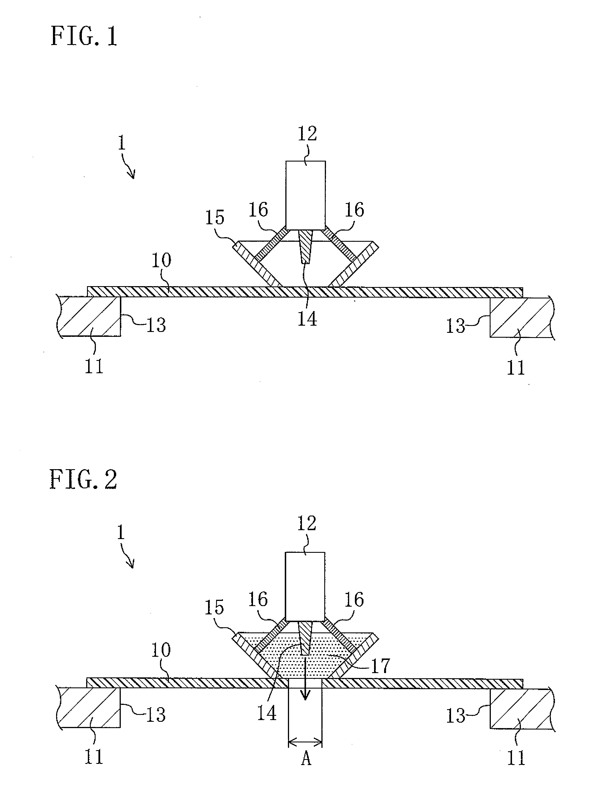
[0069]FIGS. 1 to 3 illustrate Preferred Embodiment 1 of the present invention. FIG. 1 is a cross-sectional view illustrating an enlargement of a major portion of a cutting apparatus 1 for cutting a plastic substrate 10, FIG. 2 is a cross-sectional view illustrating the plastic substrate 10 being cut, and FIG. 3 is a plan view illustrating an enlargement of a major portion of the cutting apparatus 1.

[0070]The cutting apparatus 1 for cutting the plastic substrate 10 according to Preferred Embodiment 1 includes a stage 11 on which the plastic substrate 10 is placed, and a laser emitter 12 arranged to face the stage 11. The emitter 12 is allowed to make relative movement along a surface of the plastic substrate 10 while emitting a laser, so as to laser-cut the plastic substrate 10.

[0071]Specifically, as shown in FIG. 1, the stage 11 is in the shape of, for example, a flat plate arranged to extend horizontally. The stage 11 includes an opening 13 which is opened at ...

embodiment 2

Preferred Embodiment 2

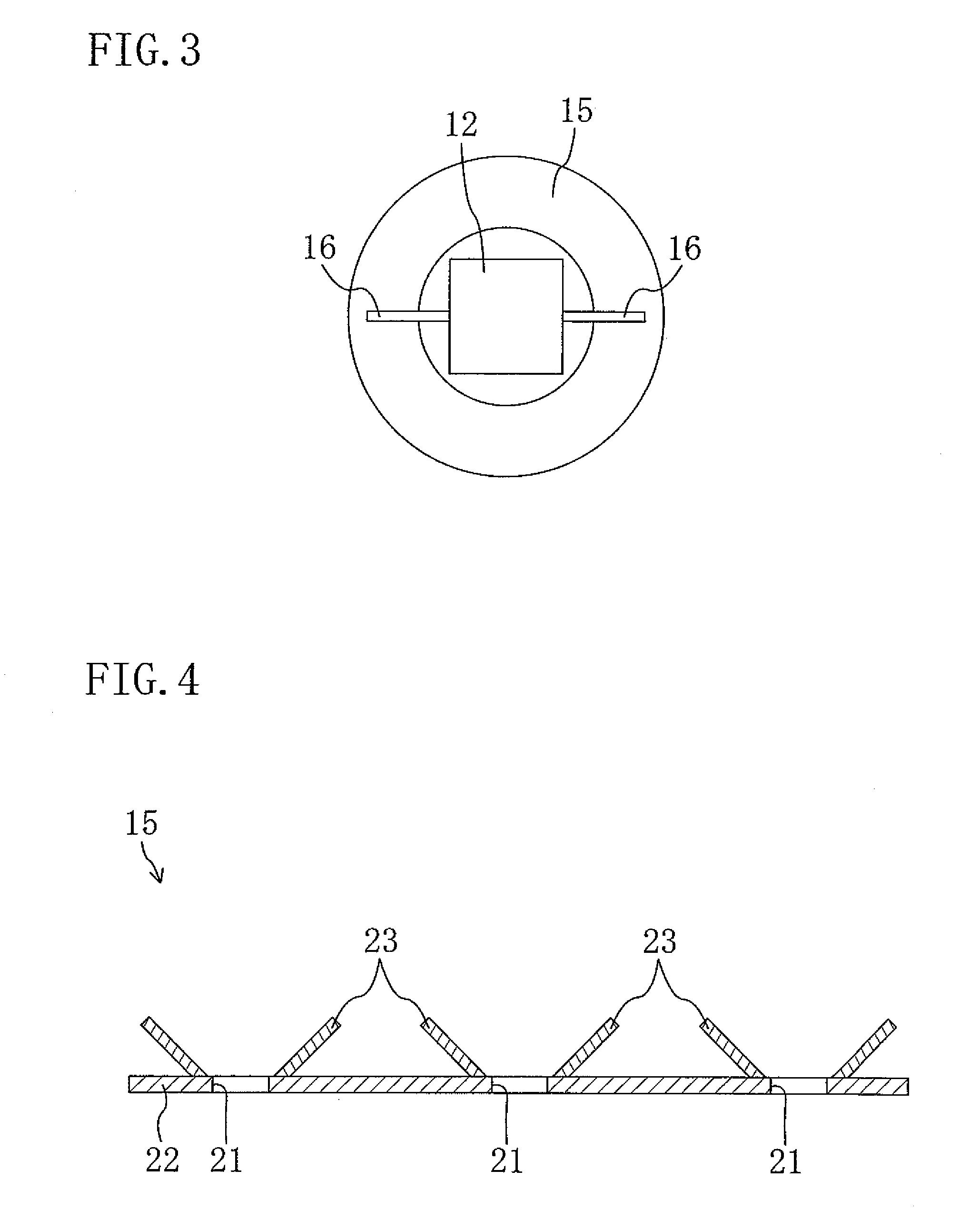
[0088]FIGS. 4 and 5 illustrate Preferred Embodiment 2 of the present invention. In the following preferred embodiments, the same components as those shown in FIGS. 1 to 3 are indicated by the same reference numerals to omit the detailed explanation.

[0089]FIG. 4 is a cross-sectional view illustrating the structure of a shield member 15 of Preferred Embodiment 2, and FIG. 5 is a perspective view illustrating the appearance of the shield member 15 of Preferred Embodiment 2.

[0090]In Preferred Embodiment 1, the shield member 15 is in the shape of a tube and is fixed to the laser emitter 12. In contrast, the shield member 15 of Preferred Embodiment 2 is in the shape of a mask.

[0091]Specifically, the shield member 15 includes, as shown in FIGS. 4 and 5, a mask member 22 which is placed on the plastic substrate 10 and has a slit 21 penetrating the mask member 22 and extending in a direction in which the plastic substrate 10 is cut, and shield plates 23 formed on the ma...

embodiment 3

Preferred Embodiment 3

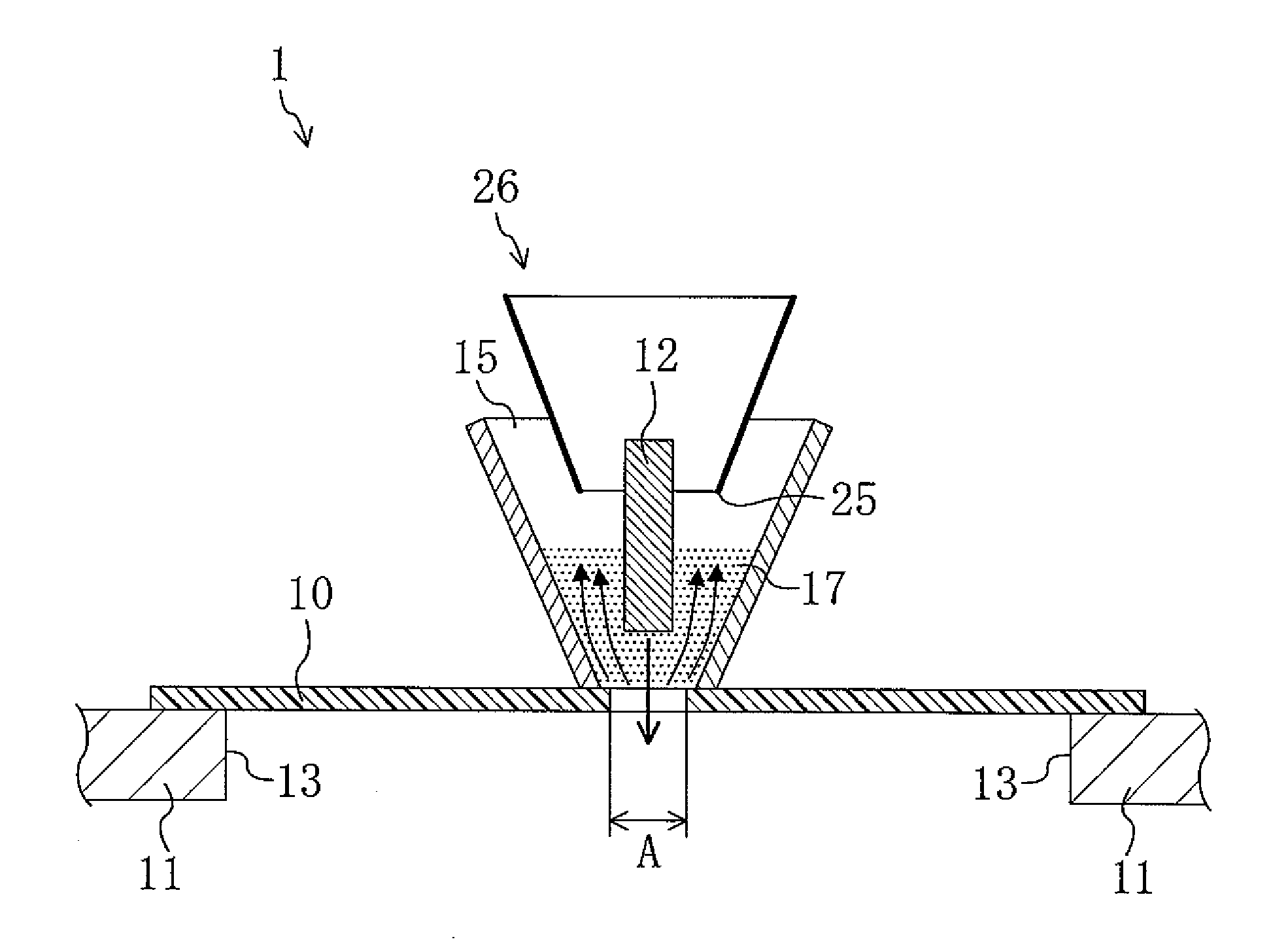
[0099]FIG. 6 illustrates Preferred Embodiment 3 of the present invention. FIG. 6 is a cross-sectional view schematically illustrating an exhaust port 25 of an exhaust system 26.

[0100]In Preferred Embodiment 1 described above, the cutting apparatus 1 includes the tubular shield member 15. In contrast, in Preferred Embodiment 3, an exhaust system 26 is provided. Specifically, the exhaust system 26 includes a tubular exhaust port 25, so that the contaminants 17 and the air are sucked through the exhaust port 25 and discharged to the outside. The exhaust port 25 is placed on a main body (not shown) of the exhaust system 26 and arranged to face the laser irradiation region A on the plastic substrate 10. The exhaust port 25 is arranged on the side of the plastic substrate 10 facing the emitter 12, and the emitter 12 is fixed to the inside of the exhaust port 25.

[0101]In cutting the plastic substrate 10 using the cutting apparatus 1 of Preferred Embodiment 3, in the s...


PUM

PropertyMeasurementUnit
thickaaaaaaaaaa
shapeaaaaaaaaaa
flexibleaaaaaaaaaa

Abstract

A laser emitter arranged to face a plastic substrate makes relative movement along a surface of the plastic substrate, while it is emitting a laser, so as to laser-cut the plastic substrate. In this process, a shield member is arranged outside a laser irradiation region on the plastic substrate.

Description

BACKGROUND OF THE INVENTION[0001]1. Field of the Invention[0002]The present invention relates to a method for cutting a plastic substrate and an apparatus for cutting a plastic substrate.[0003]2. Description of the Related Art[0004]In recent years, active research on displays, such as liquid crystal displays, organic EL devices, etc., has been conducted. In the display of this kind, a glass substrate is often used for supporting a display medium layer and the like. However, use of a flexible plastic substrate has been considered for the purpose of giving flexibility to the display itself, and reducing the thickness of the display while maintaining the strength of the substrate.[0005]For example, in the manufacture of a liquid crystal display device including a plastic substrate, TFTs, a transparent electrode, and the like are formed on one plastic substrate base, and a color filter, a transparent electrode, and the like are formed on another plastic substrate base. Then, alignment f...

Claims


Application Information

Patent Timeline
Patent Type & Authority Applications(United States)
IPC IPC(8): B23K26/16B23K26/38B23K26/42
CPCB23K26/121B23K26/16G02F1/133351B23K26/4065G02F1/133305B23K26/38B23K26/1224B23K2103/42B23K2103/50
Inventor WATANABE, NORIKO
Owner SHARP KK
Why Eureka
Try Eureka