Oil retainer cooling assembly for an electric motor

a technology of oil retainer and electric motor, which is applied in the direction of mechanical energy handling, dynamo-electric machines, supports/enclosements/casings, etc., can solve the problems of electric motor overheating and failur

Inactive Publication Date: 2010-06-17
DELPHI TECH INC
View PDF7 Cites 18 Cited by
  • Summary
  • Abstract
  • Description
  • Claims
  • Application Information

AI Technical Summary

Benefits of technology

[0007]An advantage of the present invention the is that the oil retainer cooling assembly retains the oil or heavier grease within the bearing to prevent the internal workings of the electric motor from being fouled and simultaneously cools the internal workings of the electric motor during normal operating conditions. Another advantage is that the oil retainer cooling assembly may be molded as a single piece unit. Still another advantage is that the oil retainer cooling assembly seals itself onto the support bearing with a sealing effectiveness proportional to the increase in speed of rotation of the motor shaft.
[0008]Further features and advantages of the invention will appear more clearly on a reading of the following detailed description of an embodiment of the invention, which is given by way of non-limiting example only and with reference to the accompanying drawings.

Problems solved by technology

Grease thrown inboard of the motor housing may accumulate onto the motor windings of the rotor assembly and stator, which may eventually result in a short circuit or other circuit fault causing overheating and failure of the electric motor.

Method used


Image

  • Oil retainer cooling assembly for an electric motor
  • Oil retainer cooling assembly for an electric motor
  • Oil retainer cooling assembly for an electric motor

Examples


Embodiment Construction

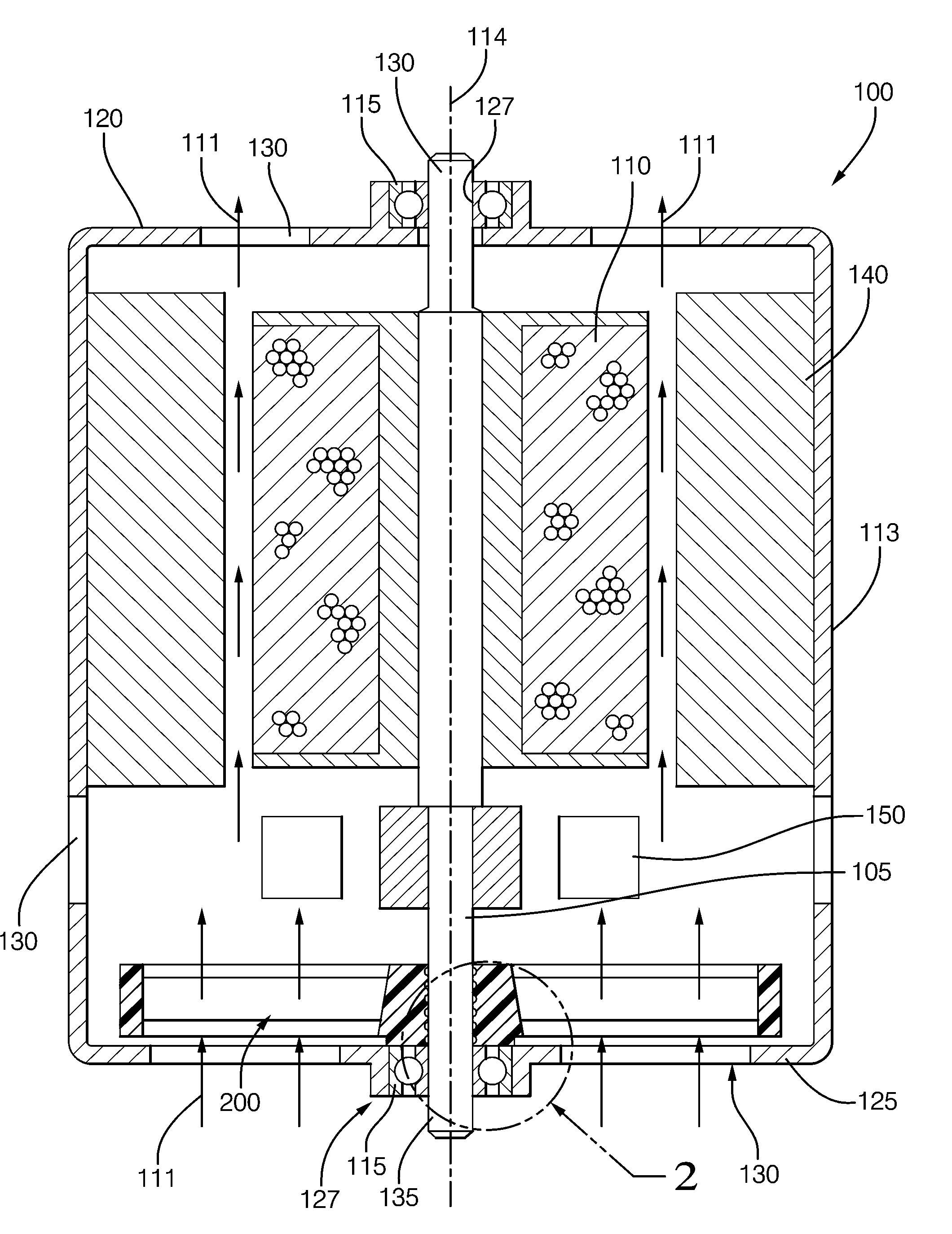
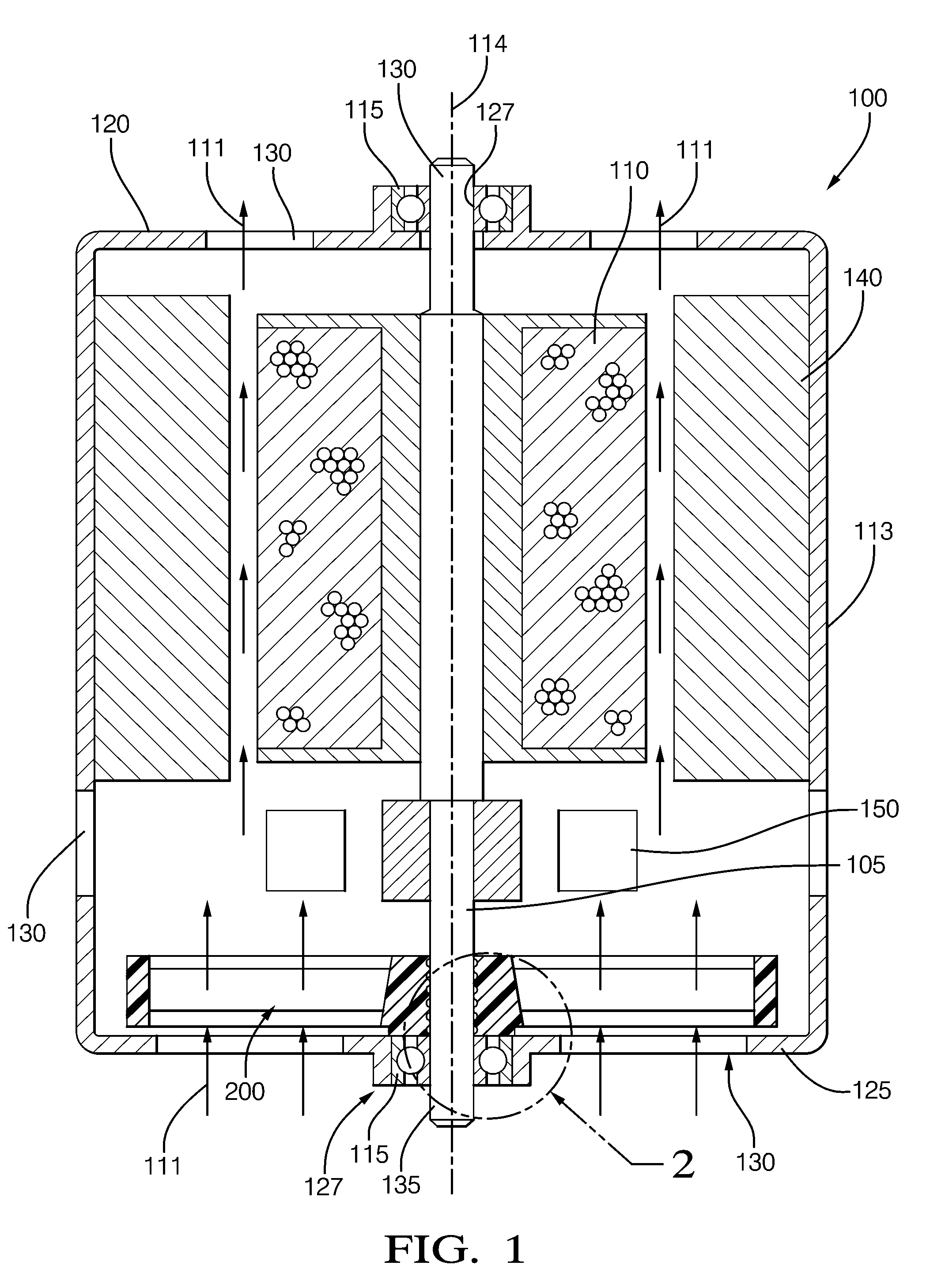
[0014]In accordance with a preferred embodiment of this invention, referring to FIGS. 1 through 4 is an electric motor assembly having an oil retainer cooling assembly 200. Shown in FIG. 1 is a cross sectional view of an electric motor 100 having an oil retainer cooling assembly 200 fixed onto motor shaft 105 between rotor assembly 110 and support bearing 115 within motor housing 113. Retainer cooling assembly 200 is a single piece unit used to retain oil in support bearing 115 and to induce air flow 111 within housing 113 to internally cool electric motor 100.

[0015]Electric motor 100 includes a housing 113 that is substantially tubular in shape along a longitudinal axis 114. Housing 113 includes a first end 120, which is the output end, and a second end 125 that is opposite that of first end 120. The first and second end 120, 125 of housing 113 is substantially perpendicular to longitudinal housing 113 and each includes an opening 127 that is concentrically located with longitudina...


PUM


Abstract

An electric motor having an oil retainer cooling assembly fixed onto the motor shaft between the rotor assembly and support bearing within the motor housing. The retainer cooling assembly is a single piece unit used to retain oil in the support bearing and to induce air flow within the housing to internally cool the electric motor. The oil retainer cooling assembly includes a hub that has a bore for the insertion and attachment of the hub to the motor shaft, a surface in sealing contact with the bearing assembly, a plurality of fan blades protruding radially from the hub, and a shoulder between the hub surface and the fan blades. The oil retainer assembly rotates with the shaft during normal operating conditions, whereby the blades induces air flow within the housing to cool the electric motor and the hub surface maintains sealing contact with bearing assembly to retain oil within the bearing.

Description

TECHNICAL FIELD OF INVENTION[0001]The invention relates to an electric motor having an oil retainer assembly; more particularly, an oil retainer assembly having fan blades for the cooling of an electric motor; still more particularly, an integrated oil retainer cooling assembly.BACKGROUND OF INVENTION[0002]Electric motors have support bearings on either ends of the motor housing to support the motor shaft. Typically, each support bearing includes a cylindrical sleeve that is press fitted into an end of the motor housing. The cylindrical sleeve includes a bore to accommodate the support and rotation of the motor shaft. The support bearing may also be that of a more complex assembly that includes an outer member that is press fitted into an end of the motor housing, an inner member that is press fitted onto the motor shaft, and friction reducing members therebetween to allow the inner member to rotate freely with respect to the outer member. The support bearings are provided with an o...

Claims


Application Information

Patent Timeline
Patent Type & Authority Applications(United States)
IPC IPC(8): H02K9/06H02K5/16
CPCH02K5/124H02K9/06H02K5/20H02K5/1732H02K5/207
Inventor PARRA, EFREN S.
Owner DELPHI TECH INC
Why Eureka
Try Eureka