Emissive type display device, semiconductor device, electronic device, and power supply line driving method

a technology of emissive type display device and electronic device, which is applied in the direction of instruments, computing, electric digital data processing, etc., can solve the problems of increasing the amplitude of an analog signal and the display characteristics being varied according to the emission time length, so as to reduce the occurrence of flicker, increase the apparent blinking frequency, and maintain the display quality

Active Publication Date: 2010-06-17
JOLED INC
View PDF23 Cites 34 Cited by
  • Summary
  • Abstract
  • Description
  • Claims
  • Application Information

AI Technical Summary

Benefits of technology

[0036]In the case of a driving system according to the embodiment of the present invention, a driving voltage is divided into a plurality of times of pulse waveform when a set peak luminance level is lower than a set value. Thus, the driving system according to the embodiment of the present invention can disperse the output of the driving voltage when a same peak luminance level is achieved over a wider range than an existing system. It is therefore possible to increase an apparent blinking frequency within an emission period, and suppress the occurrence of flicker.
[0037]In addition, the peak luminance level is controlled by controlling the driving voltage amplitude of the pulse waveform rather than the output width of the plurality of times of pulse waveform. This system makes it possible to variably control the peak luminance level in a low range while maintaining display quality. Thus, the peak luminance level can be adjusted at lower luminance than in the existing system. Even when the ambience of the display panel is dark, this function enables the peak luminance level to be lowered according to the darkness. Power consumption can be lowered at the same time.
[0038]In addition, controllable peak luminance level can be made lower than in the existing system, and therefore the range of variable peak luminance level can be extended as compared with the existing system. That is, a contrast ratio can be extended, and display quality can be enhanced.

Problems solved by technology

However, the method of controlling the dynamic range of an input signal has problems of an increase in amplitude of an analog signal output from a driving circuit due to an increase in signal amplitude of the input signal and an increase in power consumed in the driving circuit.
A method of reducing power consumption by controlling emission time length (for example Japanese Patent Laid-Open No. 2003-228331) has been proposed, but has a problem of display characteristics being varied according to the emission time length.

Method used


Image

  • Emissive type display device, semiconductor device, electronic device, and power supply line driving method
  • Emissive type display device, semiconductor device, electronic device, and power supply line driving method
  • Emissive type display device, semiconductor device, electronic device, and power supply line driving method

Examples


first embodiment

(B) First Embodiment

[0098]In the present embodiment, description will be made of a driving system suitable for a case where an organic EL panel module is mounted in a device having a low display frame rate and strongly desired to lower power consumption.

[0099]For example, the driving system is suitable for receiving a one-segment broadcast of a terrestrial digital broadcasting standard adopted in Japan. Of course, the invention itself is not limited to display of one-segment broadcast programs.

[0100]Incidentally, in the case of the one-segment broadcast, effective image resolution is given as horizontal 320 dots×vertical 240 dots or horizontal 320 dots×vertical 180 dots.

[0101]The display frame rate is given as 15 frames per second, for example. When the display frame rate is thus low, flicker tends to be visible. Accordingly, in the present embodiment, description will be made of a driving system that can lower power consumption while suppressing the occurrence of flicker.

(B-1) Exam...

second embodiment

(C) Second Embodiment

[0228]A second embodiment will next be described. In the present embodiment, a case where an image of other than one-segment broadcast programs is displayed is also assumed. That is, a driving technique is proposed which can not only control peak luminance level according to a display mode but also enhance the display quality of an image being displayed at any luminance level.

(C-1) Example of System Configuration

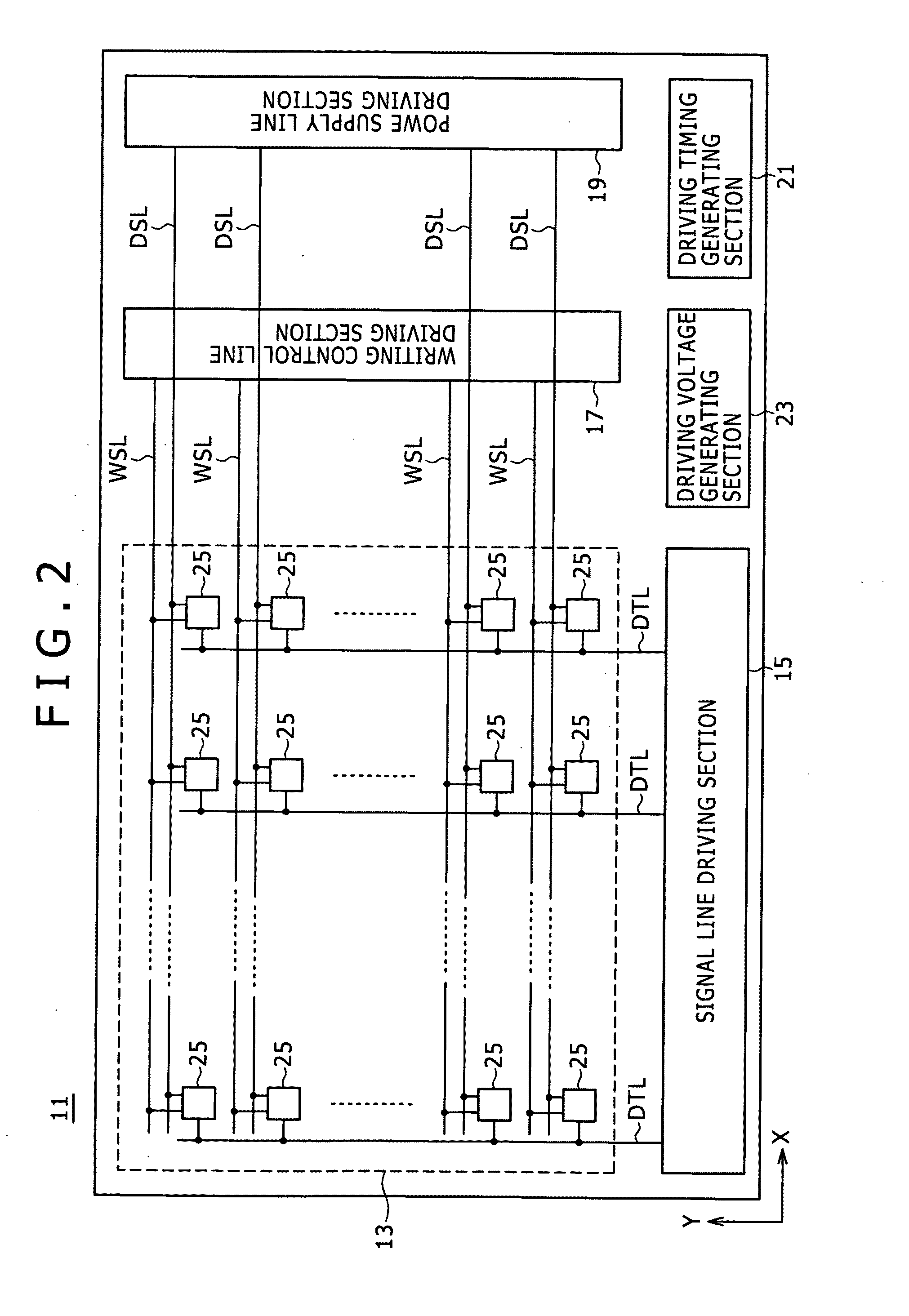
[0229]FIG. 27 shows an example of system configuration of an organic EL panel module 71 according to the present embodiment. Incidentally, in FIG. 27, parts corresponding to those of FIG. 2 are identified by the same reference numerals.

[0230]The organic EL panel module 71 has a configuration formed by arranging a pixel array section 13, a signal line driving section 15, a writing control line driving section 17, a power supply line driving section 19, a driving timing generating section 81, and a driving voltage generating section 23 on a single panel.

[0...


PUM


Abstract

An emissive type display device includes: a pixel array section having pixels ready for an active matrix driving system; a circuit for setting a peak luminance level of each display frame; and a driving circuit for variably controlling a total application period length of a driving voltage applied to a power supply line connected to each pixel and amplitude of the driving voltage so as to obtain a set peak luminance level, when the set peak luminance level is lower than a set value, the driving circuit dividing the driving voltage into a plurality of times of pulse waveform, and variably controlling the amplitude of the driving voltage at each output time according to the peak luminance level such that the amplitude of the driving voltage at least one output time is lower than a maximum driving voltage in a non-emission period.

Description

BACKGROUND OF THE INVENTION[0001]1. Field of the Invention[0002]The invention described in the present specification relates to a display panel having self-luminous elements arranged in the form of a matrix on the panel, and a panel module having a driving circuit mounted in the display panel. In the present specification, the display panel and the panel module will both be referred to as an emissive type display device. In addition, the invention in the present specification has aspects of a semiconductor device, an electronic device, and a power supply line driving method.[0003]2. Description of the Related Art[0004]One of basic performance requirements of a display is brightness (luminance). Therefore, recent displays (for example liquid crystal displays, plasma displays, and organic EL (Electro Luminescence) displays) are expected naturally to have high luminance irrespective of difference in display system.[0005]On the other hand, a display that emits light at a maximum luminan...

Claims


Application Information

Patent Timeline
Patent Type & Authority Applications(United States)
IPC IPC(8): G09G5/00
CPCG09G3/3225G09G2300/0842G09G2320/0247G09G2320/0285G09G2360/18G09G2330/028G09G2340/0435G09G2360/144G09G2360/16G09G2320/103G09G3/20G09G3/30
Inventor HASEGAWA, HIROSHIISOBE, TEPPEI
Owner JOLED INC
Why Eureka
Try Eureka