

Gas turbine engine airfoil
a gas turbine engine and air filter technology, applied in the direction of liquid fuel engines, marine propulsion, vessel construction, etc., can solve the problems of gas turbine engine performance loss, negative impact on stall margin, and reduced compressor section pressure rise ability
- Summary
- Abstract
- Description
- Claims
- Application Information
AI Technical Summary
Problems solved by technology
Method used
Image

Examples
Embodiment Construction
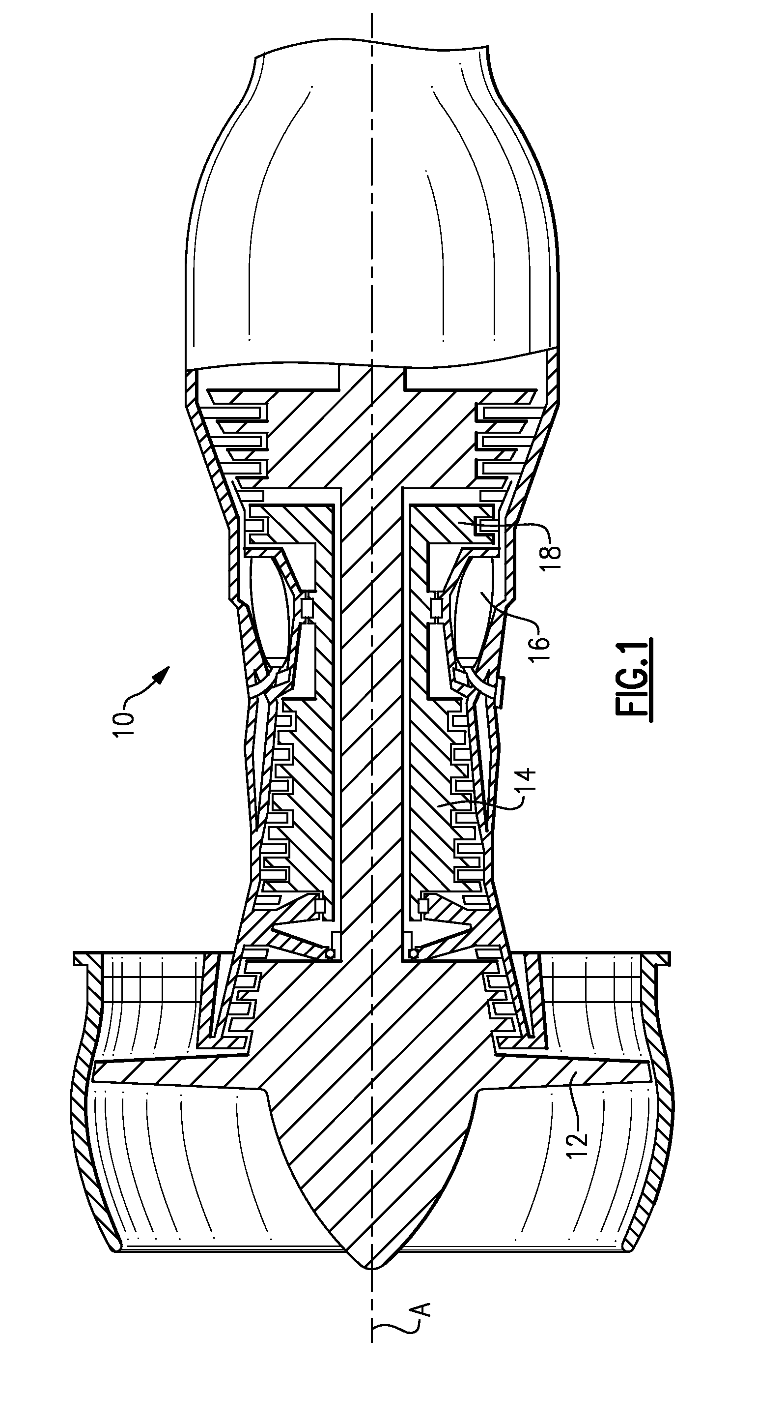
[0017]FIG. 1 illustrates an example gas turbine engine 10 that includes a fan 12, a compressor section 14, a combustor section 16 and a turbine section 18. The gas turbine engine 10 is defined about an engine centerline axis A about which the various engine sections rotate. As is known, air is drawn into the gas turbine engine 10 by the fan 12 and flows through the compressor section 14 to pressurize the airflow. Fuel is mixed with the pressurized air and combusted within the combustor 16. The combustion gases are discharged through the turbine section 18 which extracts energy therefrom for powering the compressor section 14 and the fan 12. Of course, this view is highly schematic. In one example, the gas turbine engine 10 is a turbofan gas turbine engine. It should be understood, however, that the features and illustrations presented within this disclosure are not limited to a turbofan gas turbine engine. That is, the present disclosure is applicable to any engine architecture.
[001...
PUM
| Property | Measurement | Unit |
|---|---|---|
| Fraction | aaaaa | aaaaa |
| Fraction | aaaaa | aaaaa |
| Angle | aaaaa | aaaaa |
Abstract
Description
Claims
Application Information