Revolution type compressor

a compressor and revolution technology, applied in the direction of machines/engines, liquid fuel engines, positive displacement liquid engines, etc., can solve the problems of reducing the heat exchange efficiency, reducing the performance of the refrigeration cycle, and low oil discharge performance, so as to reduce the churn of oil, and reduce the power consumption

Active Publication Date: 2010-06-17
HITACHI JOHNSON CONTROLS AIR CONDITIONING INC
View PDF32 Cites 19 Cited by
  • Summary
  • Abstract
  • Description
  • Claims
  • Application Information

AI Technical Summary

Benefits of technology

[0015]More specifically, the oil which drops to the inside of the balance weight is discharged to the space in the upper portion of the rotor without accumulating inside the balance weight, is further discharged to the outer periphery of the rotor by the action of the centrifugal force of the rotor, and is returned to the oil sump provided at the lower portion of the compressor through the clearance provided between the inside of the hermetically sealed container and the stator. Thereby, input of the compressor reduces, and the compressor with less power consumption can be obtained. Further, the oil which flows outside the compressor can be decreased, and the performance of the refrigeration cycle can be enhanced by reducing oil churn.
[0016]Further, in the case of use of the electric motor of the structure in which a permanent magnet is placed inside the rotor, leakage of the magnetic fluxes of the rotor can be reduced. Therefore, there is provided the effect of securing the electric motor efficiency and preventing increase in input of the compressor.

Problems solved by technology

The oil flowing out to the outside of the compressor adheres to the inside of the heat exchanger constructed by the refrigeration cycle, and reduces the heat exchange efficiency to decrease performance of the refrigeration cycle.
However, oil has to be discharged downward and perpendicularly to the direction of the centrifugal force by the rotor, and oil discharge performance is low.
Further, in the one in the cited document 2, the rotor in which the permanent magnet is disposed, and the balance weight which is a magnetic substance are integrated, and therefore, there is the disadvantage that the magnetic flux of the rotor leaks to reduce the efficiency of the electric motor, and increases the input of the compressor.

Method used


Image

  • Revolution type compressor
  • Revolution type compressor
  • Revolution type compressor

Examples


example 1

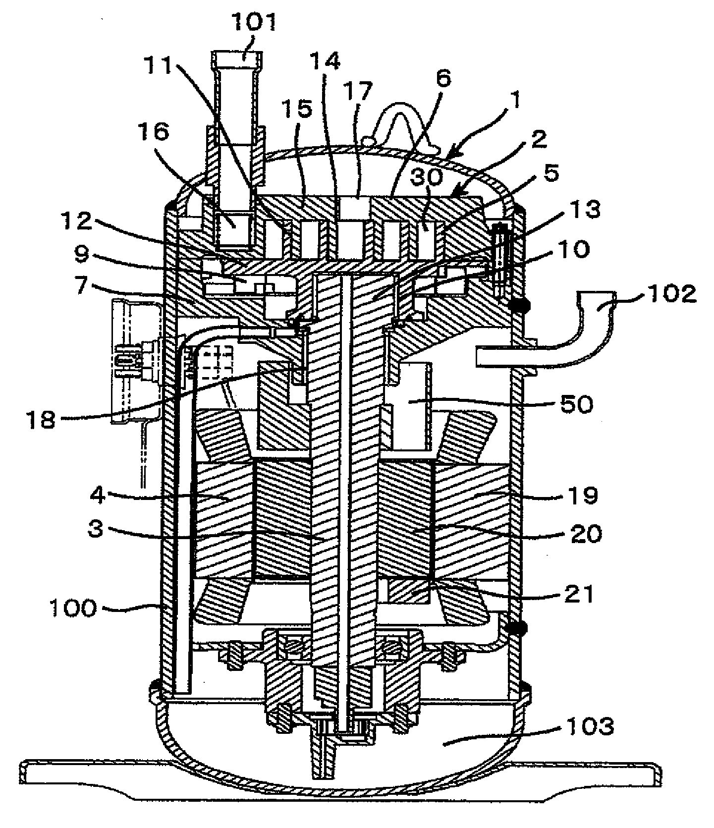
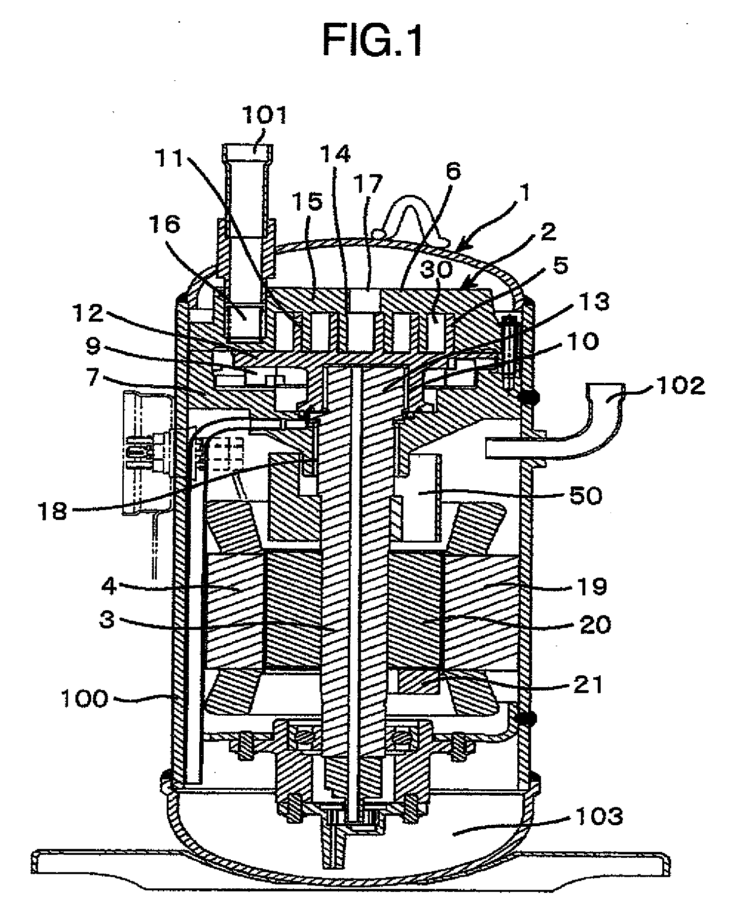
[0035]FIG. 1 shows example 1 of a revolution type compressor of the present invention, and is a general structural view of the case of being applied to a scroll compressor. A scroll compressor 1 is constructed by housing a compression mechanism 2, a drive shaft 3 and an electric motor 4 in a hermetically sealed container 100, and is of a vertical structure in which the compression mechanism 2 and the electric motor 4 are vertically arranged. The compression mechanism 2 includes an orbiting scroll 5, a fixed scroll 6, a frame 7, a drive shaft 3, a bearing 10 for orbiting scroll and an orbiting mechanism 9. Further, the compression mechanism 2 forms a compressor area 30 by combining the fixed scroll 6 and the orbiting scroll 5, and the aforementioned orbiting scroll 5 includes a spiral wrap 11 and an end plate 12. At the rear surface side of the end plate 12 of the orbiting scroll 5, the orbiting mechanism 9 which is constructed by an Oldham ring or the like is provided, and the beari...


PUM


Abstract

In a revolution type compressor using a balance weight for balancing a rotating mass, the effect of oil churn reduction is enhanced, and compressor input is reduced. A balance weight fixed to a drive shaft between a rotor of an electric motor 4 and a compression mechanism includes a weight portion in a substantially semicircular column shape for balancing a rotating mass, a cover portion which is substantially semi-cylindrical and has an opening in the vicinity of a top and bottom at an opposite side in a radial direction from the weight portion, and a hollow space surrounded by the weight portion and the cover portion. Further, a space for discharging oil is provided between the balance weight and the rotor. By the structure, reduction in oil churn, and reduction in input of the compressor are realized, and the compressor with less power consumption is obtained.

Description

BACKGROUND OF THE INVENTION[0001]The present invention relates to a revolution type compressor which is constructed by housing a compression mechanism for compressing a refrigerant, a drive shaft for driving the compression mechanism, and an electric motor for rotating the drive shaft in a hermetically sealed chamber, and fixedly providing a balance weight for balancing a rotating mass of the aforementioned compression mechanism at the aforementioned drive shaft.[0002]As the conventional revolution type compressor, there are known the ones each constructed by housing a compression mechanism for compressing a refrigerant, a drive shaft for driving the compression mechanism, and an electric motor for revolving the drive shaft in a hermetically sealed chamber (hermetically sealed container), as described in JP-A-2001-218411, JP-A-2001-234863 and JP-A-2000-73977, and the aforementioned electric motor includes a stator fixed to the hermetically sealed container, and a rotor connected to ...

Claims


Application Information

Patent Timeline
Patent Type & Authority Applications(United States)
IPC IPC(8): F04B17/03
CPCF04C18/0215F04C2240/807F04C29/028F04C23/008
Inventor NAKAMURA, SATOSHIMATSUNAGA, MUTSUNORITSUCHIYA, TAKESHICHIKANO, MASATSUGU
Owner HITACHI JOHNSON CONTROLS AIR CONDITIONING INC
Why Eureka
Try Eureka