Apparatus and method for mounting a therapeutic device

a technology of therapeutic devices and mounting devices, which is applied in the direction of application, surgical instrument support, therapy, etc., can solve the problems of ineffective requirement for physicians to be concerned with the precision with which the void is made in the cast, weak shear bond, and inability to accurately mount the transducer mounting apparatus, etc., to reduce the possibility of cast failure, reduce the size of the cast opening, and increase the strength

Inactive Publication Date: 2010-06-17
BIOVENTUS
View PDF9 Cites 26 Cited by
  • Summary
  • Abstract
  • Description
  • Claims
  • Application Information

AI Technical Summary

Benefits of technology

[0062]The invention has several advantages over prior devices and techniques. First, the apparatus has increased strength in comparison to existing ports due to the impregnation of the mesh projection by the casting material, such as resin. Second, the mesh projection provides the ability to use the fixture on smaller radius limbs. Third, the mesh projection allows for a reduction in size of the cast opening, thereby reducing the possibility of cast failure.

Problems solved by technology

This is a disadvantage as a shear bond is not as strong as other types of bonding.
Another problem associated with the prior art transducer mounting apparatus becomes apparent to physicians during the installation of the apparatus.
Moreover, it is inefficient to require the physician to be concerned with the precision with which the void is made in the cast.
Second, the medical practitioner may cut a hole in the cast and force fit a plastic transducer port into the cast, and then place the ultrasonic transducer in the port.
However, the installation of a spacer which creates a void in the cast has heretofor been delayed until a period of time has elapsed such that the danger of swelling around the affected injury site has transpired, because it has been determined that the skin within the void is prone to window edema (especially during the swelling period).

Method used


Image

  • Apparatus and method for mounting a therapeutic device
  • Apparatus and method for mounting a therapeutic device
  • Apparatus and method for mounting a therapeutic device

Examples


first embodiment

[0130]As shown in FIGS. 13 and 14, a marking template 292 is pressed against the cast 288 and centered on the mark 290 of the external location on the cast 288 of the bone fracture. The outline of the inner edges of the rectangular template opening is traced on the cast 288, and the traced portion of the cast is removed so that the opening 294 in the cast 288 exposes the skin, as shown in FIG. 14. The opening 294 in the cast 288 receives a felt pad 296 having a thickness approximately the same as the thickness of the cast. The felt pad 296 also has a cylindrical bore that receives a cylindrical felt pad 298. Felt pad 296 is provided to support the fixture 110 and to maintain pressure against the skin which helps prevent window edema (swelling) and is substantially equivalent to the pressure exerted by the cast 288 against the skin and is described in more detail below.

[0131]The template 292, and consequently the opening 294 in the cast 288, is smaller than the mesh base 112 of the f...

second embodiment

[0136]FIG. 18 illustrates the template for marking the opening 294, which is generally indicated by reference numeral 400. The template 400 is pressed against the cast 288 and centered on the mark 290 of the external location on the cast 288 of the bone fracture. The template 400 includes one or more slots 402 and a central cutout 404. In the depicted embodiment, the template 400 has four peripherally located slots 402. The cutout 404 is centered upon the mark 290, and the outline of the inner edges of the template opening is traced on the cast 288 via the slots 402. The traced portion of the cast is removed so that the opening 294 in the cast 288 exposes the skin, as shown in FIG. 14.

[0137]In some embodiments, the mesh base 112 may be used as a template to cut the opening 294. FIG. 19 illustrates the mesh base 112 resting on the cast 288. The mesh base 112 is located relative to the mark 290. In FIG. 19, the body 114 has been omitted for clarity and in order to reveal the mark 290....


PUM


Abstract

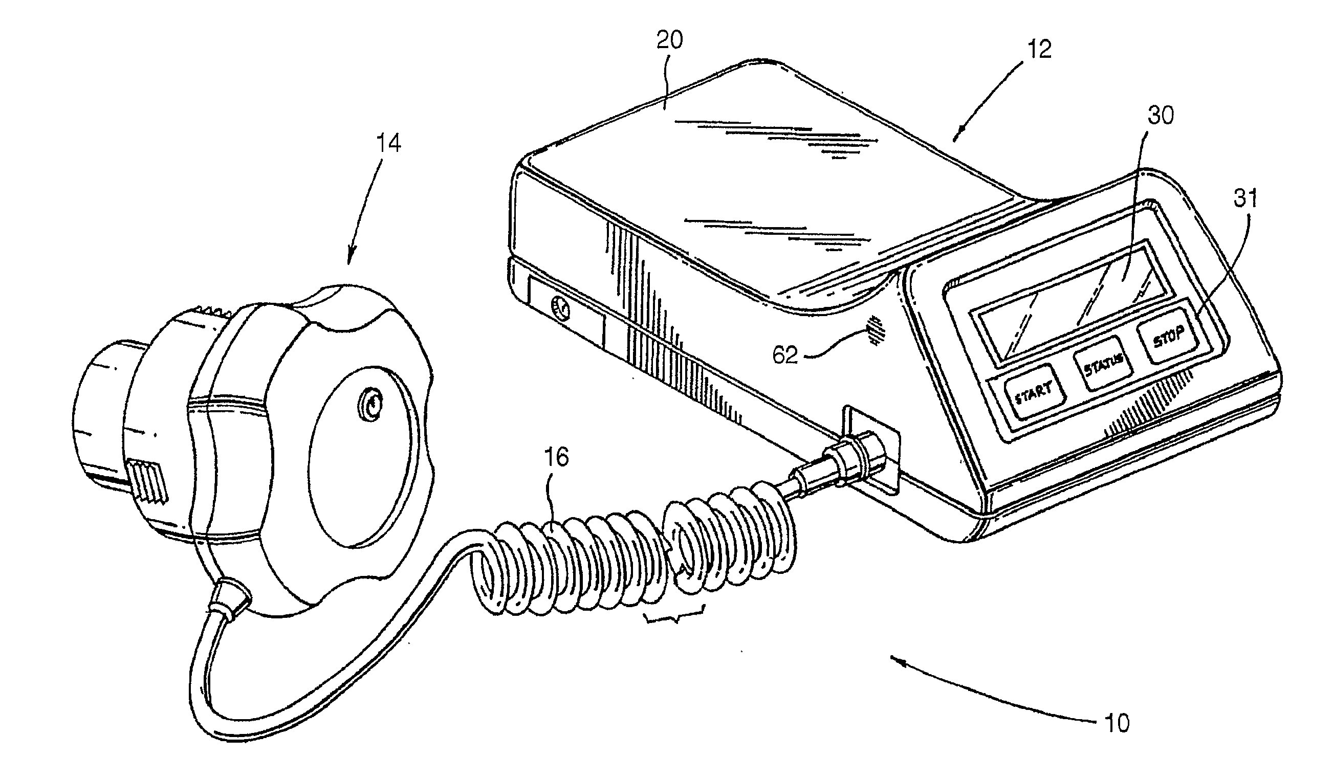
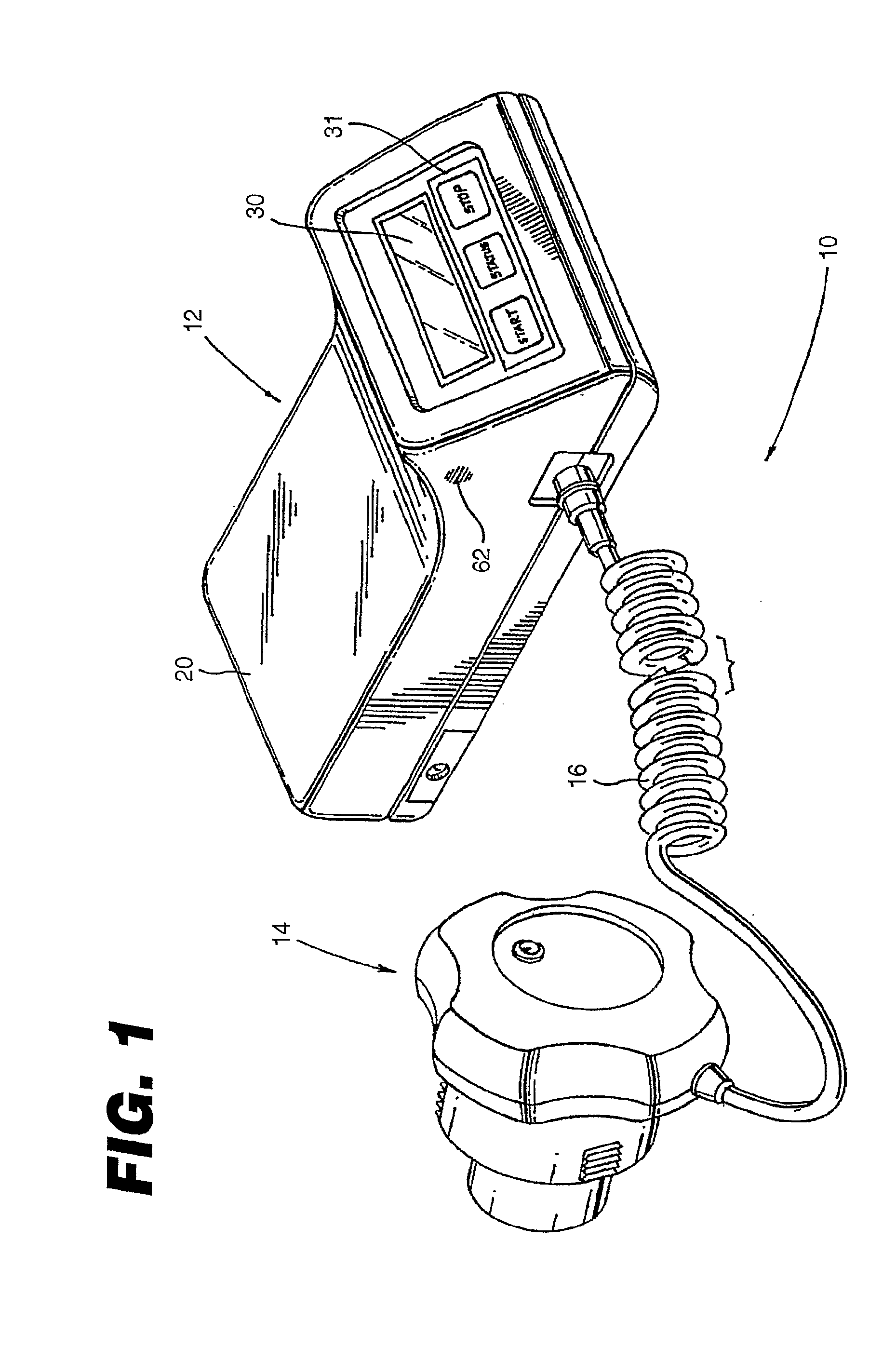
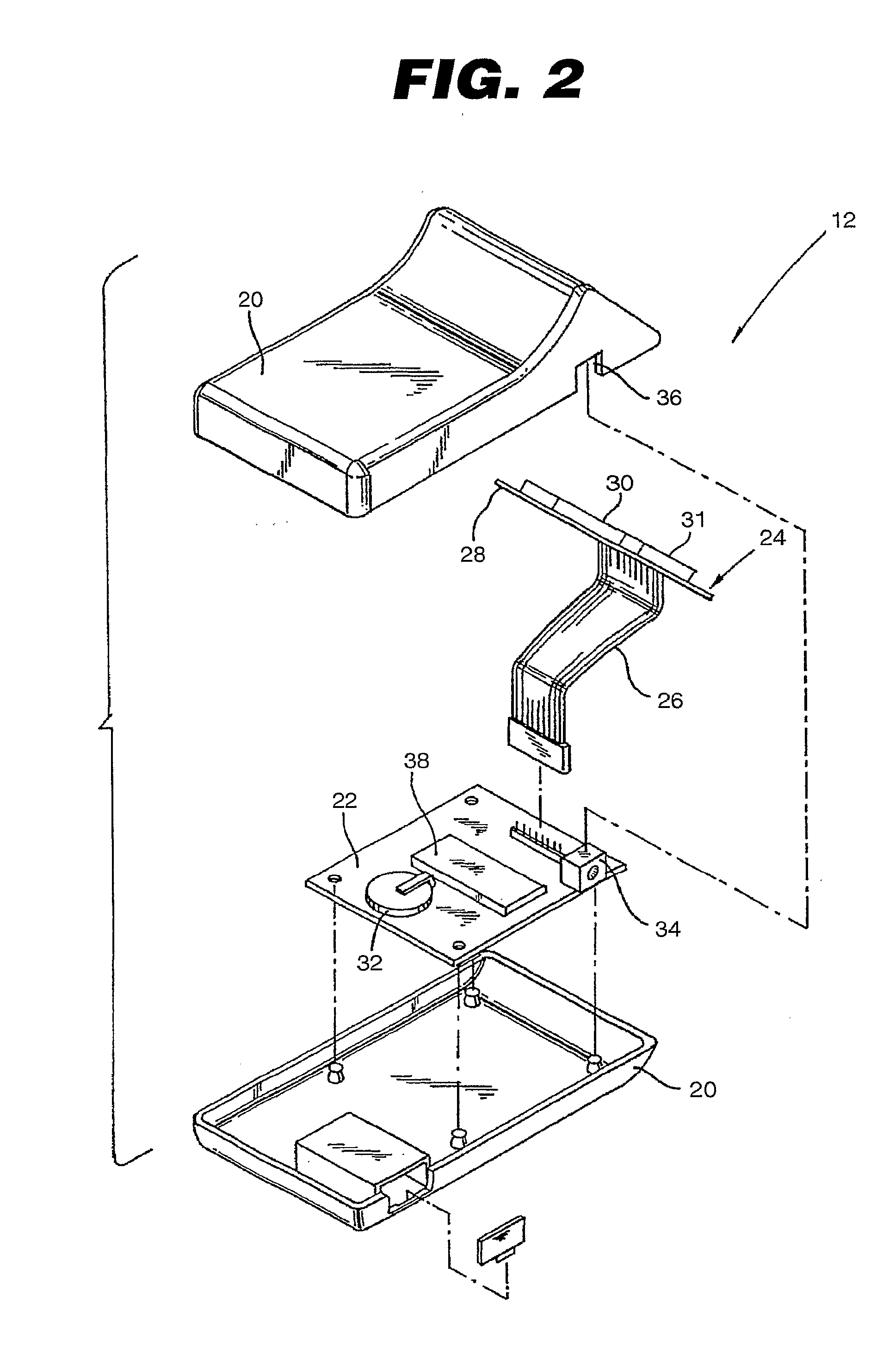
An apparatus (10) for ultrasonically treating an injury in conjunction with an orthopaedic cast (288) is disclosed. The apparatus includes a portable self-contained main operating unit (12), a support fixture (110, 520, 590, 610, 632, 672, 708, 824), an ultrasonic transducer treatment head module (14), and casting material for attaching the support fixture (110, 520, 590, 610, 632, 672, 708, 824) to the orthopaedic cast (288). The support fixture (110, 520, 590, 610, 632, 672, 708, 824) is configured and adapted for attachment to the orthopaedic cast (288) adjacent an external site corresponding to an internal injury remote from the main operating unit (12). The support fixture (110, 520, 590, 610, 632, 672, 708, 824) has a body (114) and at least one mesh projection (112, 526) extending from the body (114). The ultrasonic transducer treatment head module (14) is operatively connected to the main operating unit (12) and detachably engaged with the body (114) of the support fixture (110, 520, 590, 610, 632, 672, 708, 824). At least a portion of the casting material impregnates the mesh projection (112) to attach the support fixture (110, 520, 590, 610, 632, 672, 708, 824) to the cast (288).

Description

CROSS-REFERENCE TO RELATED APPLICATIONS[0001]This application claims the benefit of U.S. Provisional Application No. 60 / 734,245, filed Nov. 7, 2005. The disclosure of this prior application is incorporated by reference in its entirety.STATEMENT REGARDING FEDERALLY SPONSORED RESEARCH OR DEVELOPMENT[0002]Not Applicable.APPENDIX[0003]Not Applicable.BACKGROUND OF THE INVENTION[0004]1. Field of the Invention[0005]This invention relates generally to therapeutic ultrasound devices and, more particularly, to an apparatus and method for mounting a therapeutic device to an orthopaedic cast or other medical wrapping.[0006]2. Related Art[0007]The use of ultrasound to therapeutically treat and evaluate bone injuries is known. Impinging ultrasonic pulses having appropriate parameters, e.g., frequency, pulse repetition, and amplitude, for suitable periods of time and at a proper external location adjacent to a bone injury has been determined to accelerate the natural healing of, for example, bone ...

Claims


Application Information

Patent Timeline
Patent Type & Authority Applications(United States)
IPC IPC(8): A61N7/00A61F5/00
CPCA61B19/10A61N7/00A61B19/54A61B19/26A61B46/23A61B90/39A61B90/50
Inventor TANIS, KEVIN J.ARRINGTON, DEBRA ANNSCHNEIDER, JOHN B.
Owner BIOVENTUS
Why Eureka
Try Eureka