

Methods and Devices for Expanding A Spinal Canal Using Balloons
a technology of spinal canal and balloon, which is applied in the field of methods and devices for expanding a spinal canal using balloons, can solve the problems of increased medical costs, pain, and weakness in arms and/or legs, and achieve the effects of avoiding the permanence of metallic implants, and reducing the risk of infection
- Summary
- Abstract
- Description
- Claims
- Application Information
AI Technical Summary
Benefits of technology
Problems solved by technology
Method used
Image

Examples
Embodiment Construction
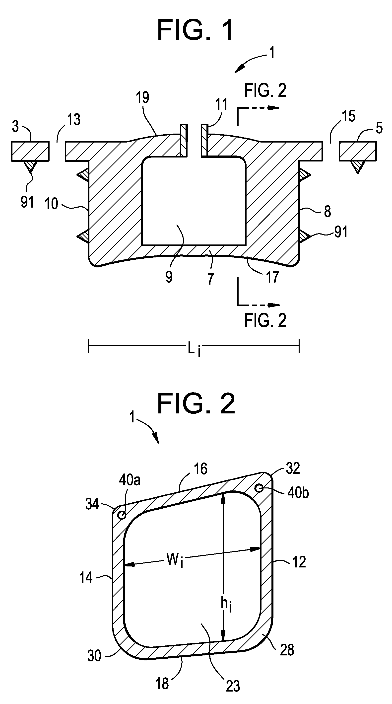
[0034]Now referring to FIG. 1, there is provided an expandable laminoplasty implant 1 for insertion into a prepared lamina having having opposing end portions and opposing faces defining a lamina space, the implant comprising:[0035]i) a first end portion 3 adapted for securement to a first end portion of a prepared lamina,[0036]ii) a second end portion 5 adapted for securement to a second end portion of a prepared lamina,[0037]iii) an intermediate portion 7 between the first and second end portions, the intermediate portion having an enclosed cavity 9, and[0038]iv) an inlet port 11 in fluid connection with the enclosed cavity.
Also in FIG. 1, the first end portion comprises a first throughhole 13 adapted for reception of a first bone fastener (not shown), while the second end portion comprises a second throughhole 15 adapted for reception of a second bone fastener (not shown). Further, the intermediate portion further comprises a concave side 17 and an opposed convex side 19. The cur...
PUM
 Abstract
Description
Claims
Application Information