Method And System For Analysis And Shape Optimization Of Physical Structures Using A Computerized Algebraic Dual Representation Implicit Dimensional Reduction

a computerized algebraic and algebraic dual representation technology, applied in multi-objective optimisation, instruments, cad techniques, etc., can solve the problems of less practical 3d computational processes, slender evolving geometry, and often thickened models in that area

Active Publication Date: 2010-06-17
WISCONSIN ALUMNI RES FOUND
View PDF6 Cites 17 Cited by
  • Summary
  • Abstract
  • Description
  • Claims
  • Application Information

AI Technical Summary

Problems solved by technology

If the results of the first analysis show that a bracket will fail under a give load, then the model is often thickened in that area.
One of the problems of conventional shape optimization processes is that the evolving geometry may become slender, e.g., beam or plate-like.
When an artifact, i.e., structural element, or portions of it, becomes slender, conventional 3D computational processes, such as finite element analysis, become less practical.
More particularly, the computational demands of the finite element analysis for such slender elements cause a significant slowdown and, in some case, inaccurate results.
Thus, while conventional 3D finite element analysis are effective for analyzing solid elements, it is less than ideal for slender elements, such as slender plates and slender beams.
Although the underlying mathematics is well understood in the art, geometric reduction involves many mathematical operations that are difficult to automate.
One proposed process for automating the aforementioned series of steps relies on the medial axis concept; however, medial axis computation is also known to be expensive and difficult to implement, especially in a 3D environment.
The issues become more challenging and problematic since some of the aforementioned computer aided design operations must be undone if the slender region grows back into a full 3D region.
Thus, “switching back and forth” between 3D analysis and dimensionally reduced analysis is not only time consuming, but can be cumbersome and thus impractical.
While frequently used, such methods are often ill-suited for microcantilever design as well as other structures having high aspect ratios.
That is, it is known that 3D FEA results in poor quality finite elements for structures having high aspect ratios, i.e., L>>W.
Generally, it has been found that conventional 3D FEA underestimates the displacement of the thin part and overestimates the stress of the thin part in response to a tip-load, for example.
Conventional ID beam analysis is also not well suited for thin parts, such as microcantilevers.
ID beam analysis poses numerous automation challenges in that it is hard to integrate within a 3D CAD environment.
Specifically, as microcantilevers become increasingly complex, computing the ID beam geometry from a 3D CAD model can be cumbersome and difficult to automate.
As noted above, explicit beam geometry construction entails modification of the 3D CAD model, and can therefore lead to product inconsistency.
Further, coupling the 1D geometry to 3D structural elements is non-trivial and requires case-by-case programming.
Finally, post-processing and visualizing the 1D analysis results within the 3D environment defeats the very purpose of 3D modeling.
However, these proposed techniques also suffer from shortcomings.
Solid-shell analysis, however, entails a priori information of the finite element mesh and therefore requires manual interaction.
Several hybrid / mixed variational methods have been proposed; however, these methods have been found to be computational inefficient compared to standard displacement based methods.
Moreover, none of the aforementioned proposed techniques are believed to deliver the same accuracy as explicit geometric reduction.

Method used


Image

  • Method And System For Analysis And Shape Optimization Of Physical Structures Using A Computerized Algebraic Dual Representation Implicit Dimensional Reduction
  • Method And System For Analysis And Shape Optimization Of Physical Structures Using A Computerized Algebraic Dual Representation Implicit Dimensional Reduction
  • Method And System For Analysis And Shape Optimization Of Physical Structures Using A Computerized Algebraic Dual Representation Implicit Dimensional Reduction

Examples


Embodiment Construction

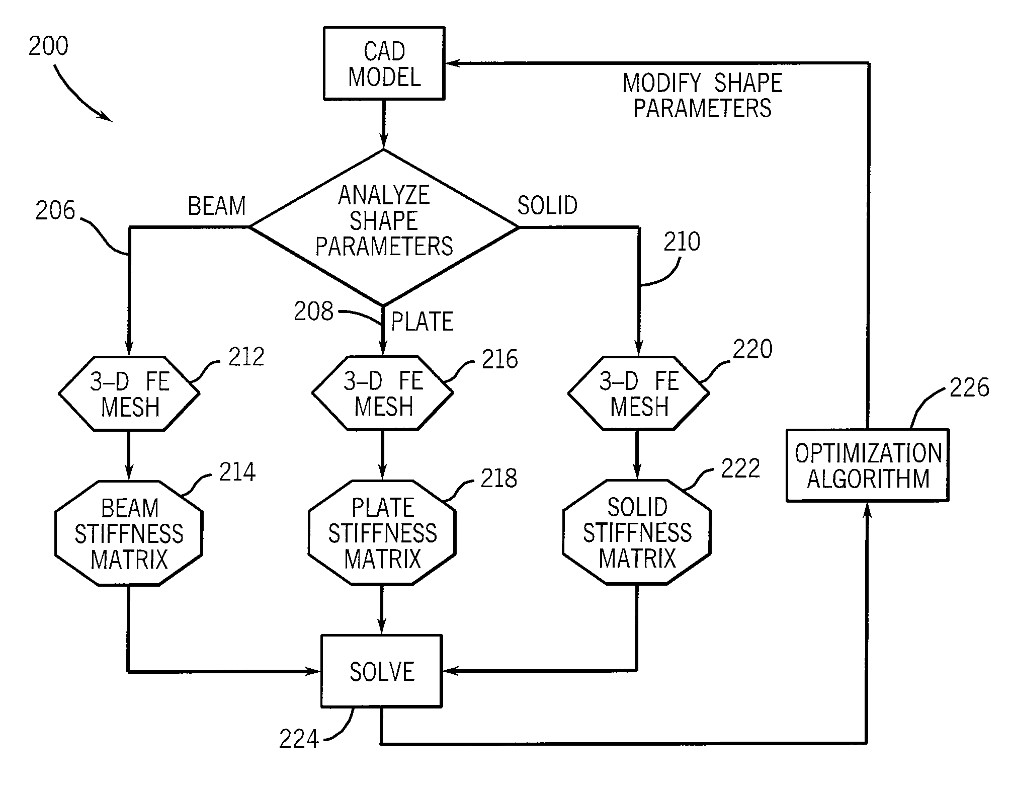
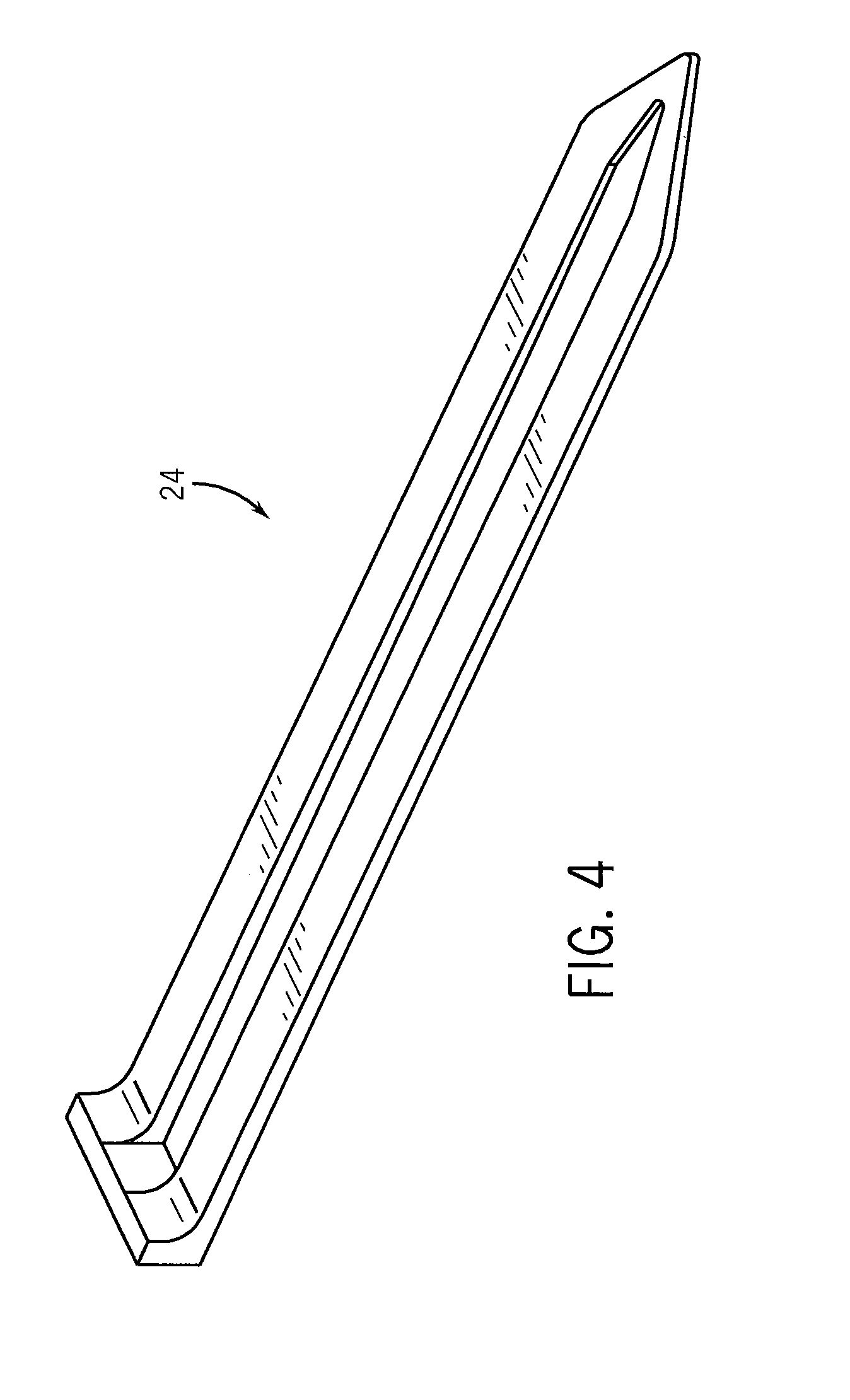
[0027]The present invention is generally directed to a computerized, iterative process for optimizing the shape of physical structures based on the simulated response of a computerized model of the physical structures to a simulated event, e.g., point load. While the invention is not so limited, the invention will be described with respect to the optimization of a microcantilever. As will be appreciated, the present invention is particularly applicable for the optimization of high aspect ratio structures, such as beams and other “thin” structures or structures having “thin” portions.

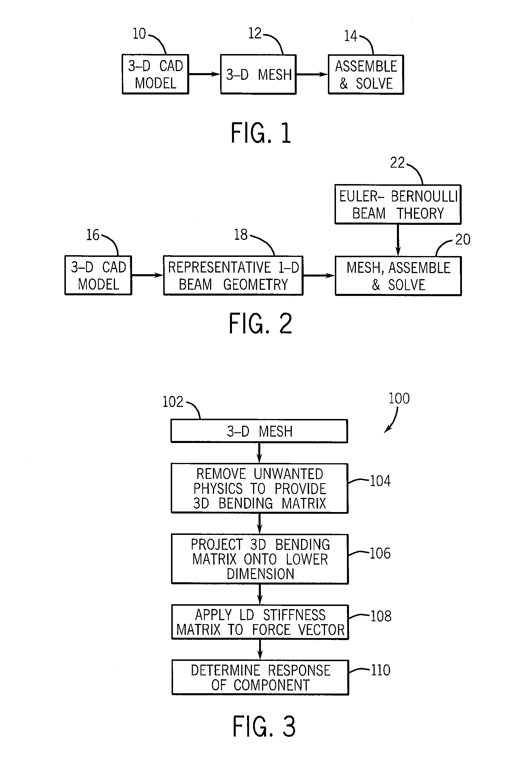
[0028]As will explained in greater detail hereinafter, the present invention provides a dual-representation structural analysis process that offers the geometric flexibility and generality of 3D FEA and the computational efficiency and accuracy of 1D beam analysis. In general, the inventive process involves the capturing of the geometry of the structure via an arbitrary 3D finite element mesh and the cap...


PUM


Abstract

A method and system for simulating and analyzing the behavior of a structural component of a computerized model in response to a simulated event to determine an optimized shape for the component is disclosed. The shape is optimized using an implicit dimensional reduction rather than an explicit geometric replacement by discarding data of a 3D discretization that has little or no bearing on the performance of the component to a simulated event. The reduced dataset is then collapsed onto a lower dimension projection that is applied over a force vector that is representative of the simulated event to determine the behavior of the component to the simulated event. Optimization tools may then be used to modify the physical attributes of the component and performance of the component once again simulated until an optimized component is determined.

Description

FIELD OF THE INVENTION[0001]The present invention relates generally to computer modeling of structures and, more particularly, to a method and system of analysis and shape optimization of physical structures using a computerized algebraic dual representation implicit dimensional reduction process rather than an explicit geometrical reduction. In one particular application, the invention applies to computer modeling and optimization of thin physical structures.BACKGROUND OF THE INVENTION[0002]Finite Element Analysis (FEA) is a software modeling tool used by design engineers to pre-test a virtual (computerized) model prior to physical construction of the model. In general, FEA tools are used to assess the behavior or performance of a computer model, or element of the model, in response to agent. To do so, the FEA tools break down a 3D model into multiple elements. The mathematical problem, representative of the agent, is applied to each element and solved, and then the elements are th...

Claims


Application Information

Patent Timeline
Patent Type & Authority Applications(United States)
IPC IPC(8): G06F17/10
CPCG06F2217/08G06F17/5018G06F30/23G06F2111/06
Inventor SURESH, KRISHNANJORABCHI, KAVOUSDANCZYK, JOSH
Owner WISCONSIN ALUMNI RES FOUND
Why Eureka
Try Eureka