
Method of treating water and aqueous systems in pipes with chlorine dioxide

a technology of chlorine dioxide and aqueous systems, applied in the direction of biocide, water/sewage treatment by oxidation, halogen oxide/oxyacid, etc., can solve the problems of chlorine dioxide not being stored in compressed form or in relatively high concentration solutions, unable to prevent the surroundings of the generation system, and unable to store chlorine dioxid

Active Publication Date: 2010-06-24
EVONIK OPERATIONS GMBH
View PDF4 Cites 25 Cited by
  • Summary
  • Abstract
  • Description
  • Claims
  • Application Information

AI Technical Summary

Benefits of technology

[0048]Some particular advantages of the present invention will be described in more detail hereinafter.

Problems solved by technology

Owing to the explosive tendency of gaseous chlorine dioxide (c>300 g / m3) and chlorine dioxide solutions (c>26 g / l), chlorine dioxide cannot be stored in compressed form or in solutions of relatively high concentration.
Despite the use of the above-mentioned procedures, in the event of incorrect operation of the chlorine dioxide generation systems (e.g., due to loss of dilution water or by failure of the pressure control) spontaneous decomposition (explosion) of chlorine dioxide can occur, or chlorine dioxide may, owing to leakage or breakage of separation surfaces between the chlorine-dioxide-containing solution and the environment, lead to hazards in the surroundings of the generation systems.
The use of diluted starting chemicals, which can lead to chlorine dioxide solutions with a concentration of less than 6 g / l and therefore sacrifice the relatively high time-specific generation rates of the chlorine dioxide systems, also cannot prevent the hazard to the surroundings of the generation systems wherein the MAK value (maximum workplace concentration) of 0.1 ppm is exceeded in the event of incorrect operation.
Clearance in this case means depressurizing and emptying the system-bearing pipe.

Method used


Image

  • Method of treating water and aqueous systems in pipes with chlorine dioxide
  • Method of treating water and aqueous systems in pipes with chlorine dioxide
  • Method of treating water and aqueous systems in pipes with chlorine dioxide

Examples


example 1

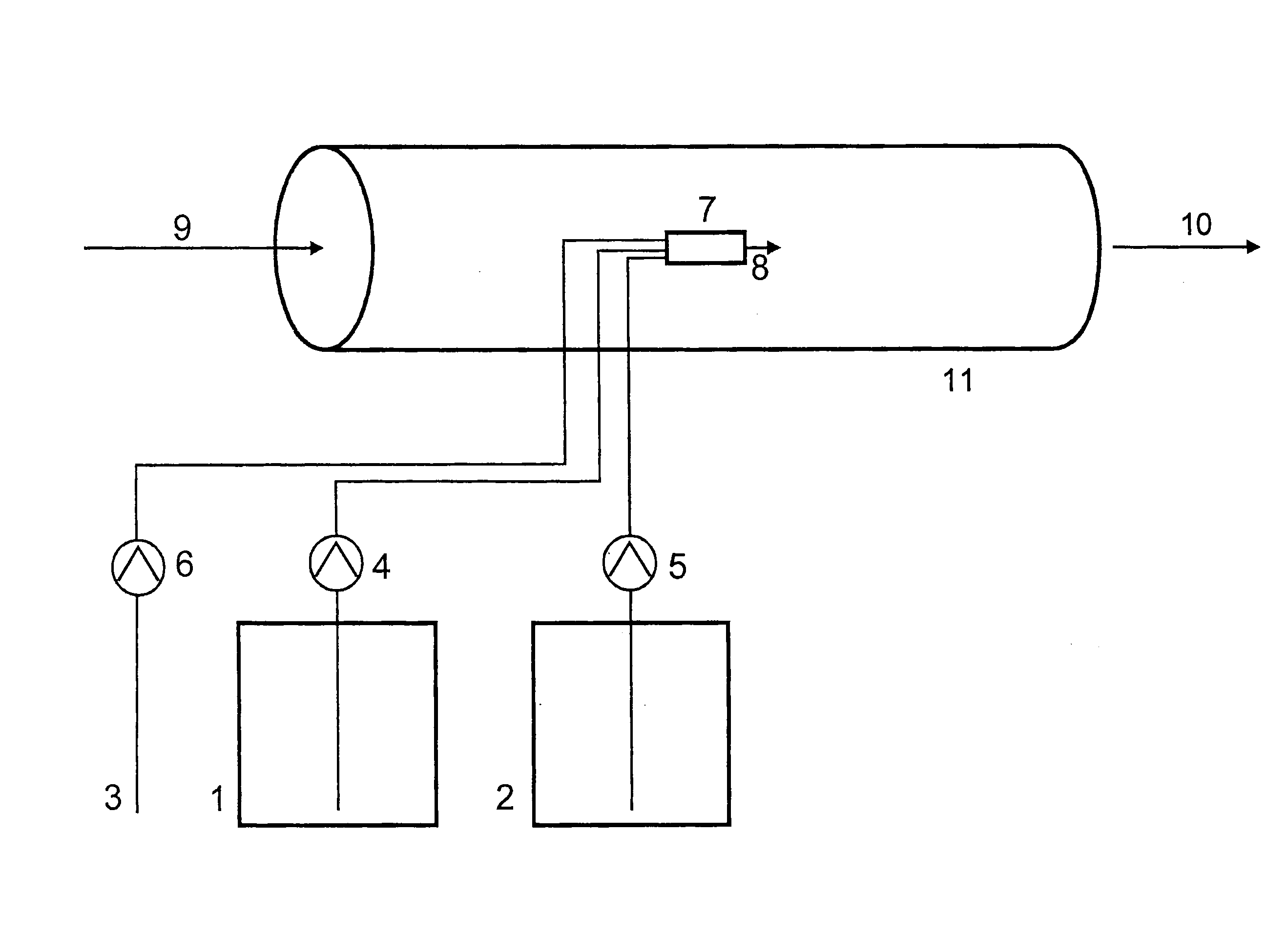
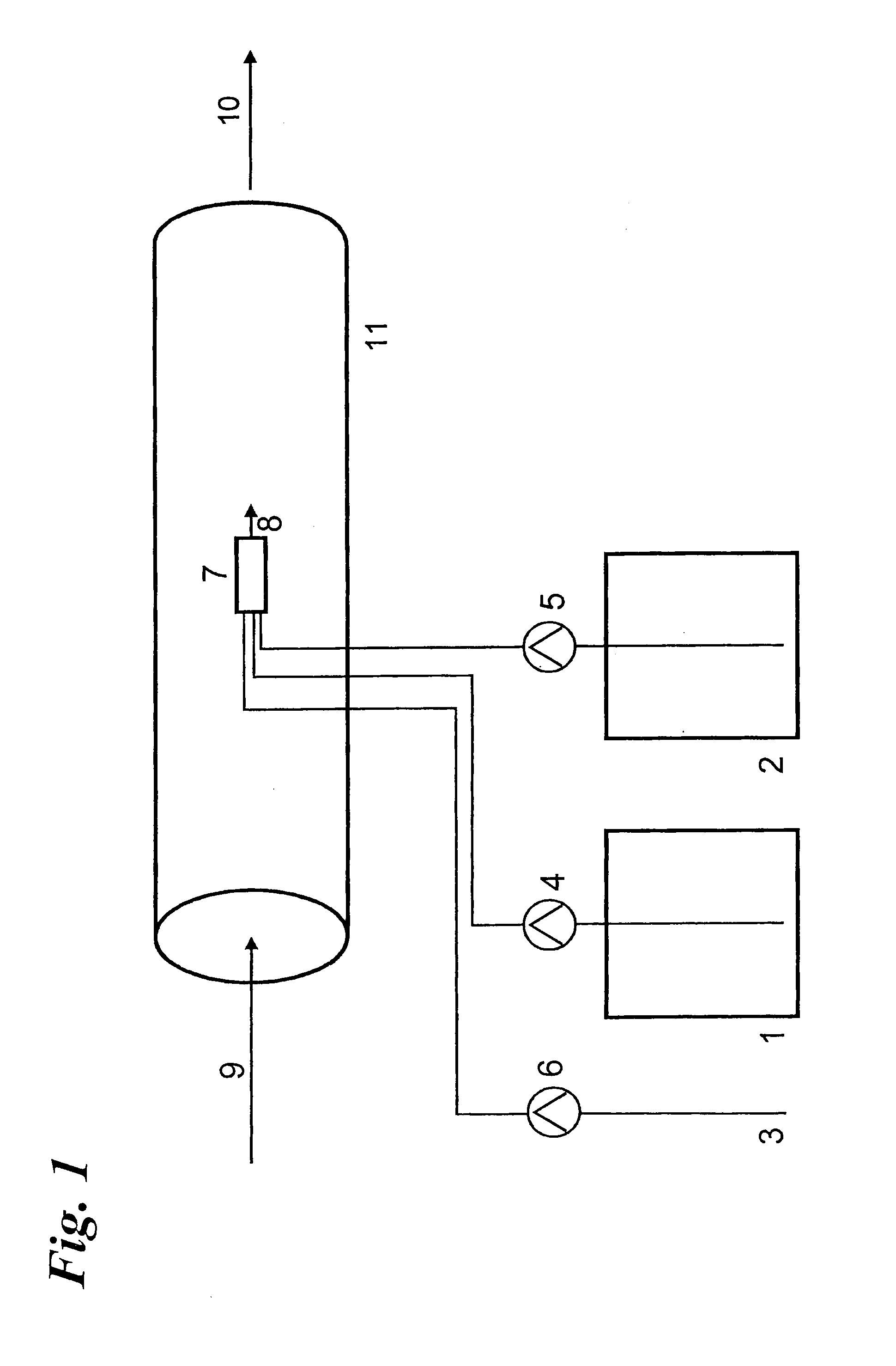
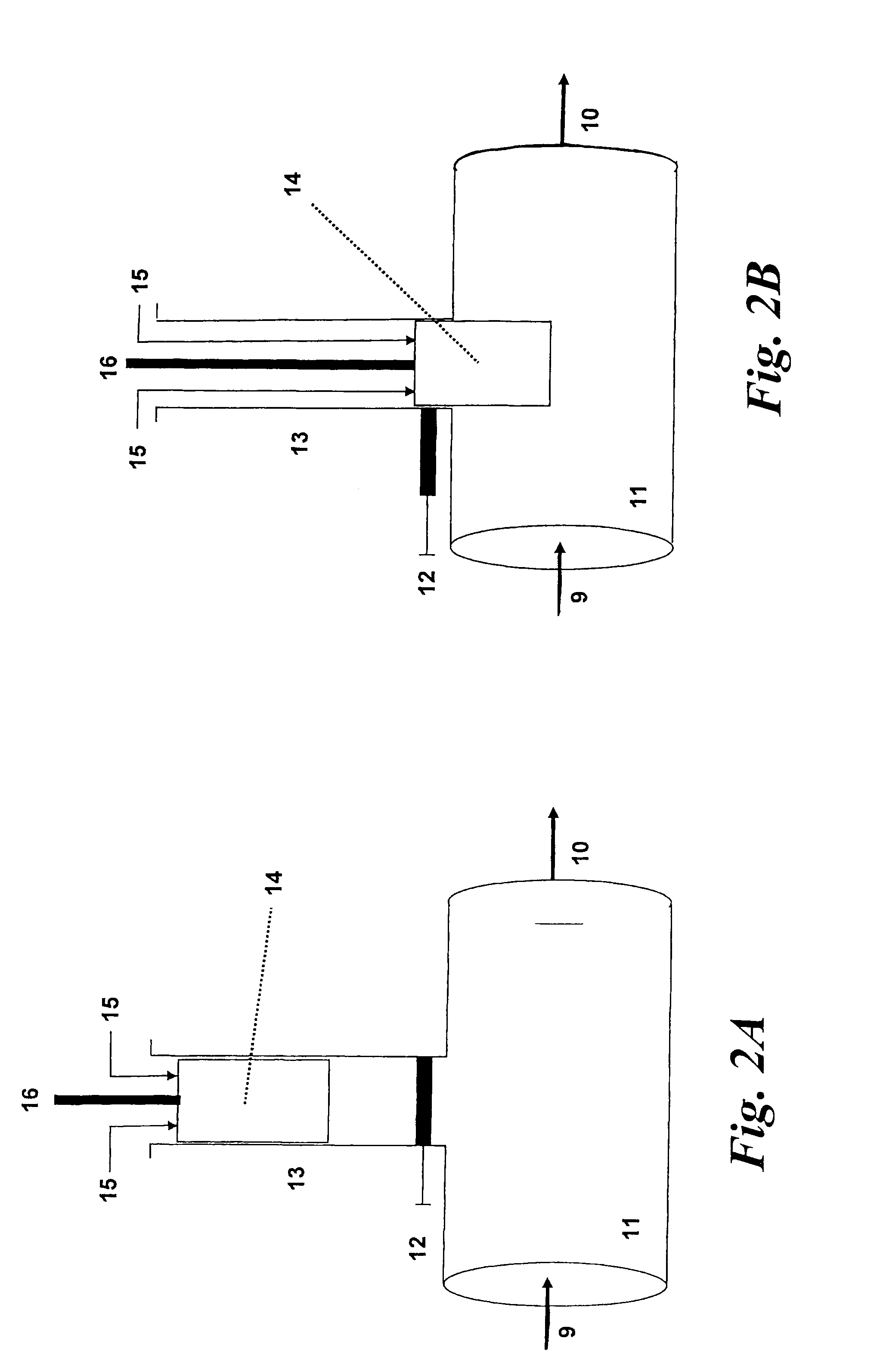
[0085]The device described in FIGS. 2a and 2b was used. The mobile device 14 having the reactor 7 contained therein was situated with shutoff element 12 open in the pipe 11 through which the system flowed and was thereby in the operating state. The pipe 11 had a diameter of 600 mm and the system to be treated 9 in the pipe 11 was surface water which was fed at a mass flow rate of 1000 m3 / h via pipe 11 to a treatment unit. The pressure in the pipe 11 was 6.2 bar. Via the feed lines 15, 5.9 l of a 25% strength sodium chlorite solution and 5.3 litres of a 32% strength hydrochloric acid solution were fed per hour to the reactor. The reactor had a free volume of 0.075 litre and the residence time of the reaction mixture in the reaction space was 0.4 minute. 11.1 litres of chlorine dioxide solution having a content of 92 g / l were delivered per hour via the reaction space outlet 8 into the system to be treated 9 (surface water) flowing round the reactor 7. This corresponded to a calculated...


PUM


Abstract

The present invention relates to a method of treating water and an aqueous system, situated in a pipe, with chlorine dioxide (ClO2), the method including generating ClO2 in a reaction space such that the generated ClO2 is completely surrounded by a system to be treated, and delivering the ClO2 generated in the reaction space to the system to be treated which is situated in the pipe, wherein the system surrounding the reaction space is the system to be treated, the reaction space is a component of a mobile device and the mobile device can be introduced into the pipe, in which the system to be treated is situated, and removed again independently of the pressure state of the pipe containing the system to be treated, and the reaction space is situated in the pipe containing the system to be treated.

Description

BACKGROUND OF THE INVENTION[0001]1. Field of the Invention[0002]The invention relates to a method of treating water and aqueous systems (hereinafter called the systems to be treated) in pipes with chlorine dioxide (ClO2).[0003]2. Discussion of the Background[0004]Chlorine dioxide can be used in water treatment and for treating aqueous systems because of its high bactericidal, virucidal and algicidal activity. Aqueous systems are used in a multiplicity of industrial processes such as, in the food industry, in brewing processes, in the drink industry and in paper making, inter alia, as transport medium, as heating and cooling medium and for washing purposes. The transport of such aqueous systems typically proceeds primarily in pipes. Generally, biological growth in these systems can be restricted by using biocides such as, chlorine dioxide. Owing to the explosive tendency of gaseous chlorine dioxide (c>300 g / m3) and chlorine dioxide solutions (c>26 g / l), chlorine dioxide cannot ...

Claims


Application Information

Patent Timeline
IPC IPC(8): C02F1/76
CPCA01N59/00C01B11/024C02F1/76C02F2303/20C02F2303/04C02F2303/14C02F2303/02C02F1/50
Inventor DUVE, HANS
Owner EVONIK OPERATIONS GMBH
Learn More