Vehicle-Mounted Equipment Carrier With One-Piece, Fixed Position Frame Construction

a technology of fixed position frame and equipment carrier, which is applied in the field of vehicle-mounted equipment carrier, can solve the problems of adding cost and complexity to equipment carrier, extra components adding cost, and adding cost to connecting and using the carrier, so as to add cost and complexity, add cost, and add cost

Active Publication Date: 2010-06-24
PEDRINI
View PDF23 Cites 6 Cited by
  • Summary
  • Abstract
  • Description
  • Claims
  • Application Information

AI Technical Summary

Benefits of technology

[0004]The pivoting arm and leg assemblies add cost and complexity to the equipment carrier. In addition to the securing means, the arm and leg assemblies must be connected. Each assembly must be adjusted, often independently of the other, to the proper rotational alignment to interface the vehicle. The extra components add cost and the independent adjustments of each assembly add complexity to connecting and using the carrier. Thus, in certain applications, it would be desirable to provide a vehicle-mounted equipment carrier having a one-piece, fixed position frame construction that has a reduced cost, eliminates stress transfer points, and results in easier setup and use.
[0005]In accordance with one aspect of the invention, a vehicle-mounted equipment carrier is provided that includes a one-piece frame having a central section to which an upper portion for holding the equipment and a lower portion for engaging the vehicle are connected. Each of the upper and lower portions is connected in a fixed relationship to the central section by virtue of the one-piece construction of the frame. Thus, it is a feature of the invention to provide an equipment support which does not require adjustments between the leg and arm assemblies, and thus eliminates the cost and complexity associated with separate manufacture and assembly of such components.
[0006]According to another aspect of the invention, the one-piece frame of the equipment carrier may have a hollow interior. Thus, it is another feature of the invention that the equipment carrier will be light-weight for ease of setup and use.
[0007]It is another feature of the invention to provide low-cost construction by molding the frame as a single-member.

Problems solved by technology

The pivoting arm and leg assemblies add cost and complexity to the equipment carrier.
The extra components add cost and the independent adjustments of each assembly add complexity to connecting and using the carrier.

Method used


Image

  • Vehicle-Mounted Equipment Carrier With One-Piece, Fixed Position Frame Construction
  • Vehicle-Mounted Equipment Carrier With One-Piece, Fixed Position Frame Construction
  • Vehicle-Mounted Equipment Carrier With One-Piece, Fixed Position Frame Construction

Examples


Embodiment Construction

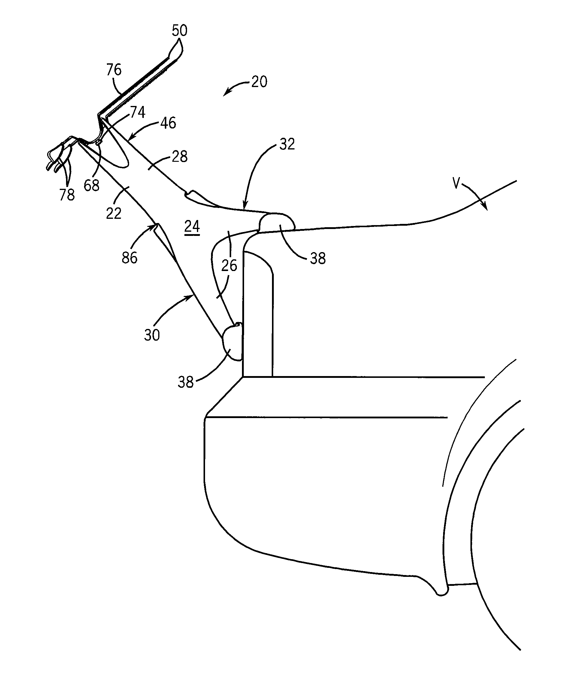
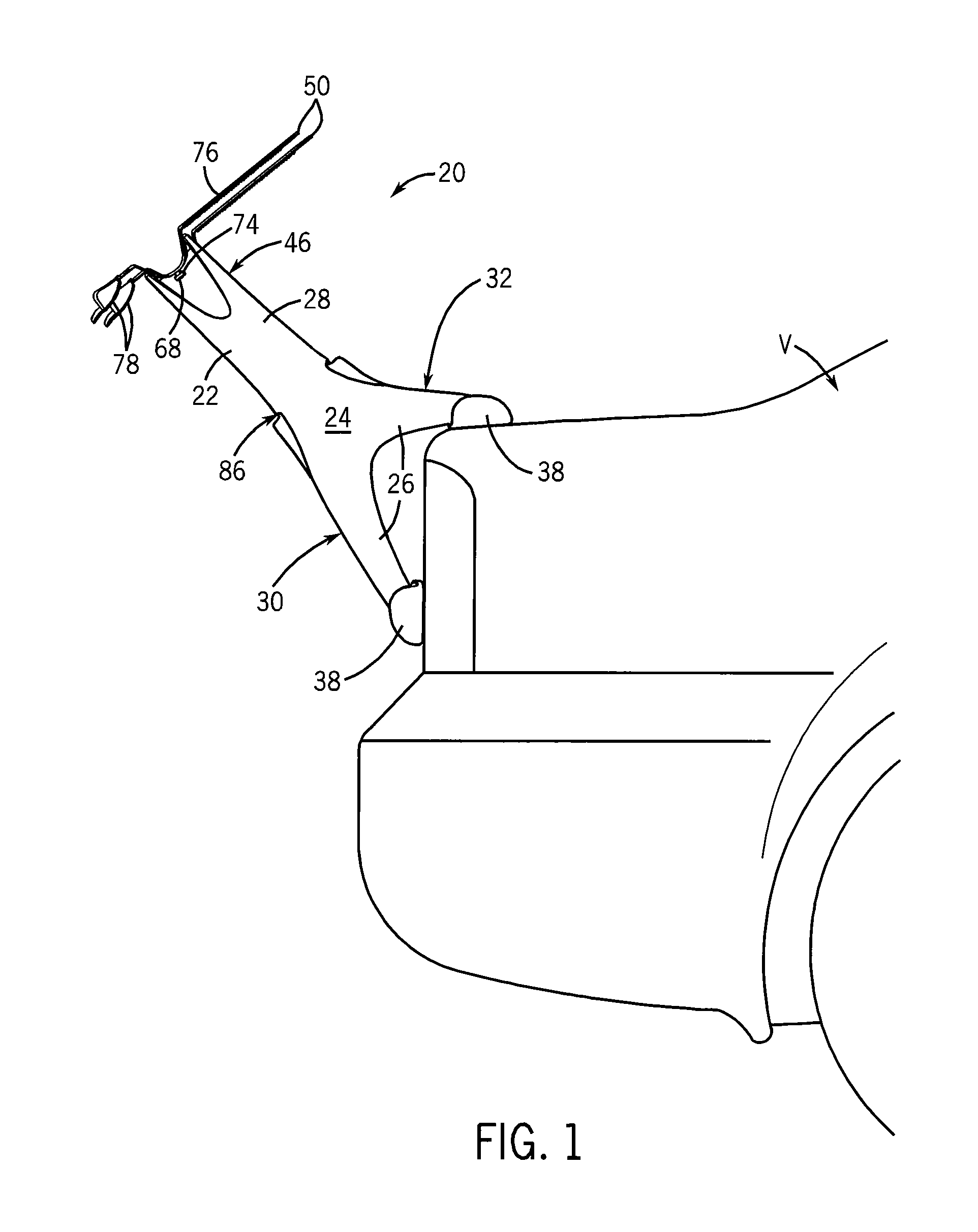
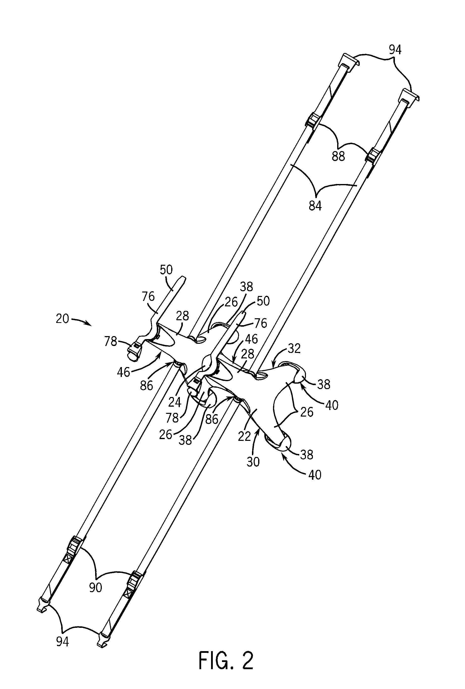
[0037]Specific embodiments of the present invention will now be further described by the following, non-limiting examples which will serve to illustrate various features of the invention. With reference to the drawing figures in which like reference numerals designate like parts throughout the disclosure, a representative embodiment of the present invention is shown in FIGS. 1-5 as an equipment carrier or support 20 configured for mounting to a vehicle, shown at V.

[0038]The equipment support 20 includes a single, one-piece frame member 22. The frame member 22 is preferably a molded-plastic member to simplify manufacture, and may have a hollow cross section to reduce the cost of the equipment support 20. The frame member 22 includes a central portion 24 from which at least one upper portion, for example an arm 28, and at least one lower portion, for example a leg 26, extends. The frame member 22 preferably includes a first lower portion and a second lower portion, for example a first...


PUM

PropertyMeasurementUnit
angleaaaaaaaaaa
thicknessaaaaaaaaaa
weightaaaaaaaaaa

Abstract

A vehicle-mounted equipment carrier includes a single-piece frame member. The vehicle-engaging and equipment-engaging members extend outward from a central portion. Optionally, the equipment carrier may be mounted in at least a first and second operational orientation. The interior of each equipment support is hollow such that one equipment support may be stacked within another. Straps pass through and are secured to the frame member. The straps are further connected to a vehicle to secure the frame member to the vehicle.

Description

CROSS-REFERENCE TO RELATED APPLICATIONS[0001]This application claims priority to U.S. provisional application Ser. No. 61 / 140,404, titled “Single Frame Member Equipment Support Assembly” and filed on Dec. 23, 2008, the entire contents of which is incorporated herein by reference.BACKGROUND AND SUMMARY OF THE INVENTION[0002]The subject matter disclosed herein relates to a vehicle-mounted equipment carrier, such as a bicycle rack, and more particularly to an equipment carrier of the type that is typically mounted to the trunk or tailgate area of a vehicle.[0003]As is known to those skilled in the art, a vehicle-mounted equipment carrier, such as a bicycle carrier, typically contacts the vehicle with at least two leg assemblies. The leg assemblies may consist of a single leg, a pair of legs, or have a cross-member between the legs, resulting in a u-shaped leg assembly. The equipment carrier also includes a support arrangement such as a pair of spaced apart arms, configured to receive a...

Claims


Application Information

Patent Timeline
Patent Type & Authority Applications(United States)
IPC IPC(8): B60R11/00B23P17/04
CPCY10T29/49826B60R9/10B60R9/06
Inventor PEDRINI
Owner PEDRINI
Why Eureka
Try Eureka