Zone Determination by Combining Signal Strength with Topological Factors

a topological factor and signal strength technology, applied in direction finders using radio waves, instruments, reradiation, etc., can solve problems such as rfid technologies, affecting productivity and morale, and easy by-passing of basic security technologies, etc., to achieve smooth reduction of signal strength over distance. , the effect of combining signal strength and topological factors

Inactive Publication Date: 2010-06-24
AL QEMMAH LETECHA AL MALOUMAT CO SIMTIX +1
View PDF9 Cites 31 Cited by
  • Summary
  • Abstract
  • Description
  • Claims
  • Application Information

AI Technical Summary

Benefits of technology

[0010]Active RFID technologies are used to tag assets and people within buildings or open areas, such as parking lots or military bases. Part of the functionality in this embodiment identifies, preferably within a few meters, the real-time location (RTLS) of the tag, i.e. to create

Problems solved by technology

But these basic security technologies are easily by-passed.
But these technologies quickly begin to affect productivity and morale.
Some

Method used


Image

  • Zone Determination by Combining Signal Strength with Topological Factors
  • Zone Determination by Combining Signal Strength with Topological Factors
  • Zone Determination by Combining Signal Strength with Topological Factors

Examples


example topology

[0017

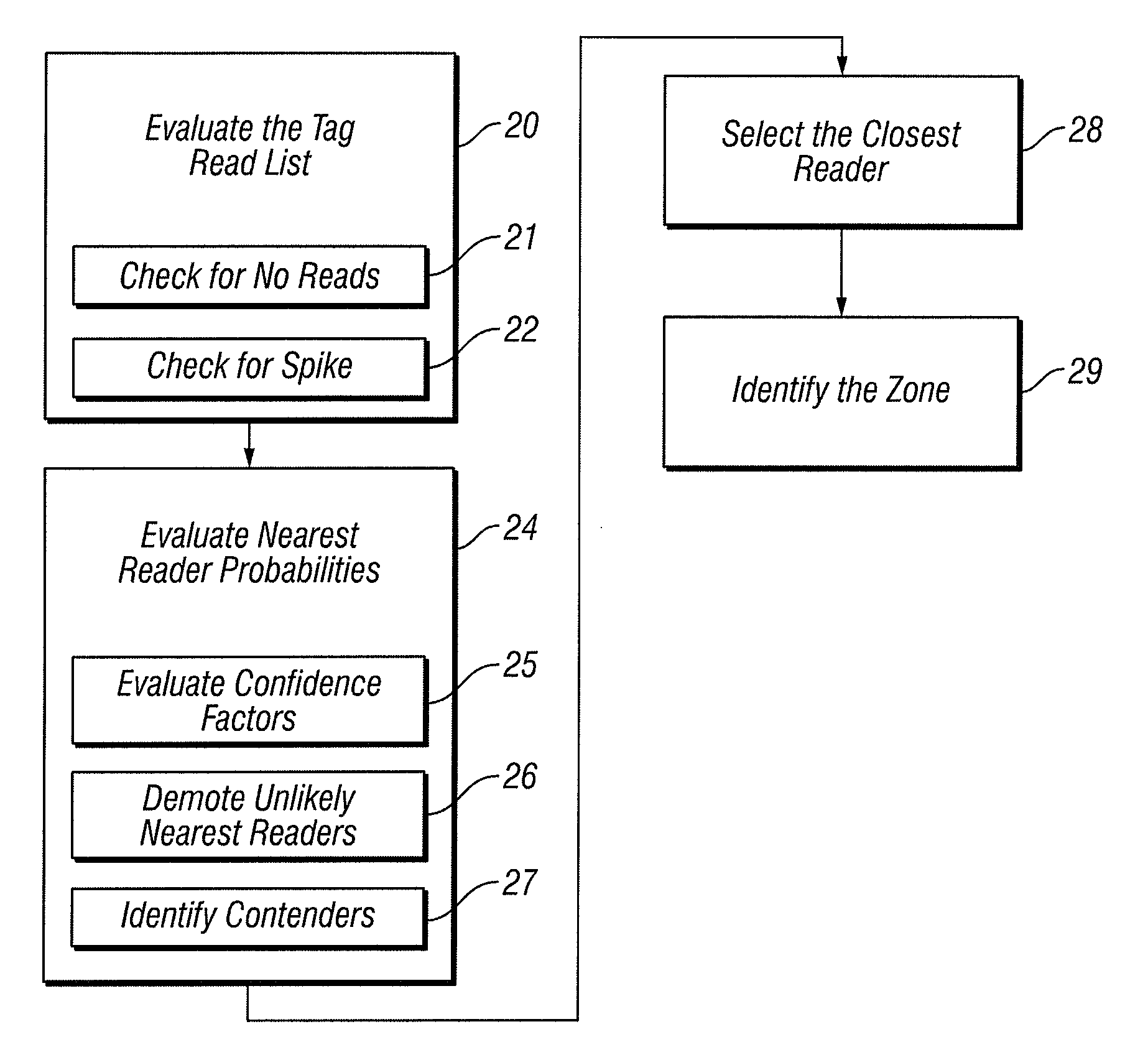
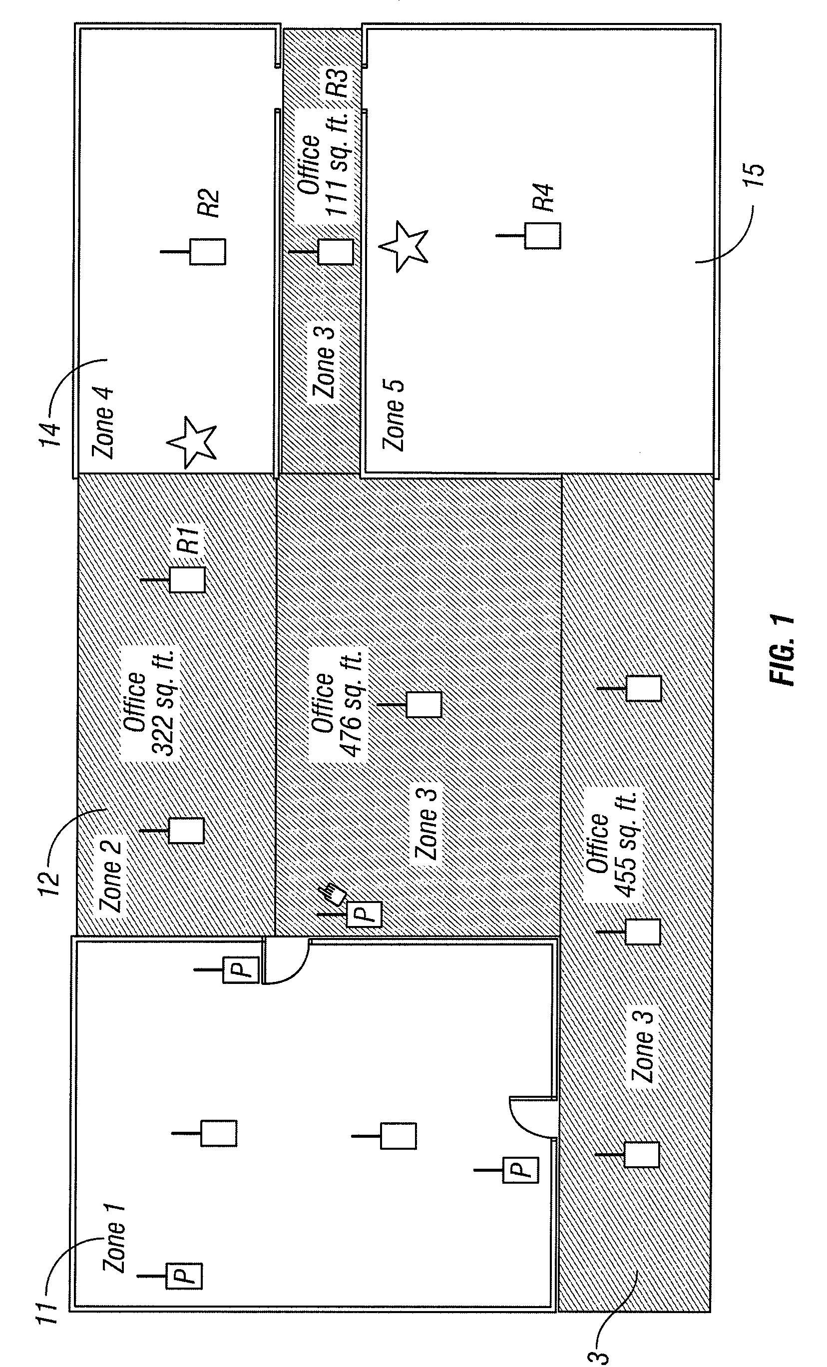
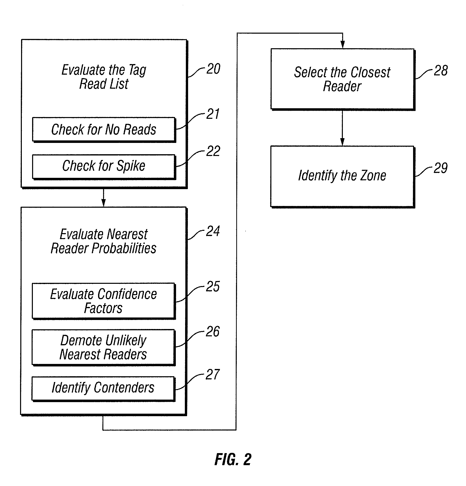
[0018]FIG. 1 is a block schematic diagram that provides an example of a real world zone topology. In the example of FIG. 1, the topology presents many of the challenges that the zone determination algorithm must accommodate.

[0019]Some of the important characteristics evident in this floor plan include:[0020]Zone 1 (11) is not an open zone, i.e. it can only be accessed by going through one door, but people can leave from two doors.[0021]Zone 2 (12) and Zone 3 (13) are not separated by any physical barriers, and users are free to walk between the zones unimpeded.[0022]Zone 3 is a non-rectangular shape.[0023]Someone in Zone 2 is highly unlikely to jump to either Zone 4 (14) or Zone 5 (15) without going through Zone 3, but it is not impossible to do so.[0024]Parts of Zone 5 are dead, where the tags in Zone 5 are not read by Zone 5, but may be read by Zone 4.

[0025]The Challenge

[0026]Most RFID systems use one or both of two basic approaches to determine the location of a tag:

[0027]1....


PUM


Abstract

Active RFID technologies are used to tag assets and people within buildings or open areas, such as parking lots or military bases; and to identify, preferably within a few meters, the real-time location (RTL) of the tag, i.e. to create a real-time location system, known as an RTLS. A novel and complex algorithm is provided that combines signal strength computations with factors that incorporate physical realities, such as walls and floors, to determine a tag's real-time location more accurately.

Description

BACKGROUND OF THE INVENTION[0001]1. Technical Field[0002]The invention relates to protecting sensitive facilities by tracking the movement of objects and persons within such facilities. More particularly, the invention relates to zone determination by combining signal strength with topological factors.[0003]2. Description of the Prior Art[0004]Advanced security within facilities was, until recently, was restricted to highly sensitive establishments such as embassies, banks and intelligence groups. The vast majority of facilities simply had perimeter control, with security staff controlling who could enter a building, but once inside people could (with a little tenacity) access almost any area.[0005]Over the past 20 years, with an increased awareness of intellectual and asset theft, many facilities introduced access control badges to restrict access within a facility. But these basic security technologies are easily by-passed. An intruder, for example, can use a stolen (or borrowed) ...

Claims


Application Information

Patent Timeline
IPC IPC(8): H04Q5/22
CPCG01S5/0278H04Q2213/13003G01S5/14
Inventor AINSBURY, ROBERTADAWIYA, IMMADOMAR, KHALID
Owner AL QEMMAH LETECHA AL MALOUMAT CO SIMTIX
Why Eureka
Try Eureka