[0088]Of course, a single LUT may be calculated which incorporates the output values for each input value which result in the off-axis luminance plot described by the bold line in the figure. A key
advantage of the present invention is that the analysis step preceding the LUT selection step effectively allows the points at which the output values “hop” from one LUT plot to another to be shifted in dependence on the data values of the other colour components in the pixel being modified, providing greatly increased scope for optimising the preservation of a wider range of colours and increased maximum brightness.
[0089]If the reduced computing and memory resource required by a method which only uses a single LUT to provide the off-axis to on-axis luminance characteristic shown by the bold line in FIG. 10 is desirable, then the output values of the LUT may be calculated using the following method which is based on that disclosed in the co-pending application GB 0916241.3 for use in a privacy type display: The on-axis and off-axis (e.g. at 50° inclination) luminance of the display may be measured for all input data values, or indeed for a selection of the possible data values and the remainder interpolated, of a particular colour channel. From this data, the average combined average off-axis and on-axis luminance for all possible combinations of data values on two pixels of that colour may be inferred. If these values are normalised, and each combination plotted as a point in off-axis to on-axis luminance space, the result is as shown in FIG. 17 (a).
[0090]A series of these points can be selected according to the required on-axis and off-axis luminance for each input
data value of the LUT. FIG. 17 (b) shows the same
population of available average on-axis and off-axis luminance points for the pixel data combinations, with a bold
black line joining the points which have been selected for the LUT. In this case, the points have been selected to provide an normalised on-axis luminance for each input
data value which is as close to the normalised on-axis luminance which the input
data value would itself produce, and a normalised off-axis luminance which is as close as possible to the normalised on-axis luminance, while avoiding any sharp changes in off-axis luminance between points with similar on-axis luminance, which would cause image artefacts to the off-axis viewer. Any off-axis to on-axis luminance trace within the space of available points may be selected but traces of the form shown in FIG. 17(b) have been shown to provide good colour shift improvement. The output values of the LUT can then be determined as being the combination of two data values which produced each selected point of FIG. 17(b). This method may be performed for each colour channel of the display, providing a means to achieve good colour shift improvement with only one LUT required for each colour channel, each LUT consisting of a pair of output data values for each input data value.
[0091]After the analysis, LUT selection and data modification steps have been performed on all pixel data values in the input image, the modified image is output from the modified display
control electronics to the display. An example
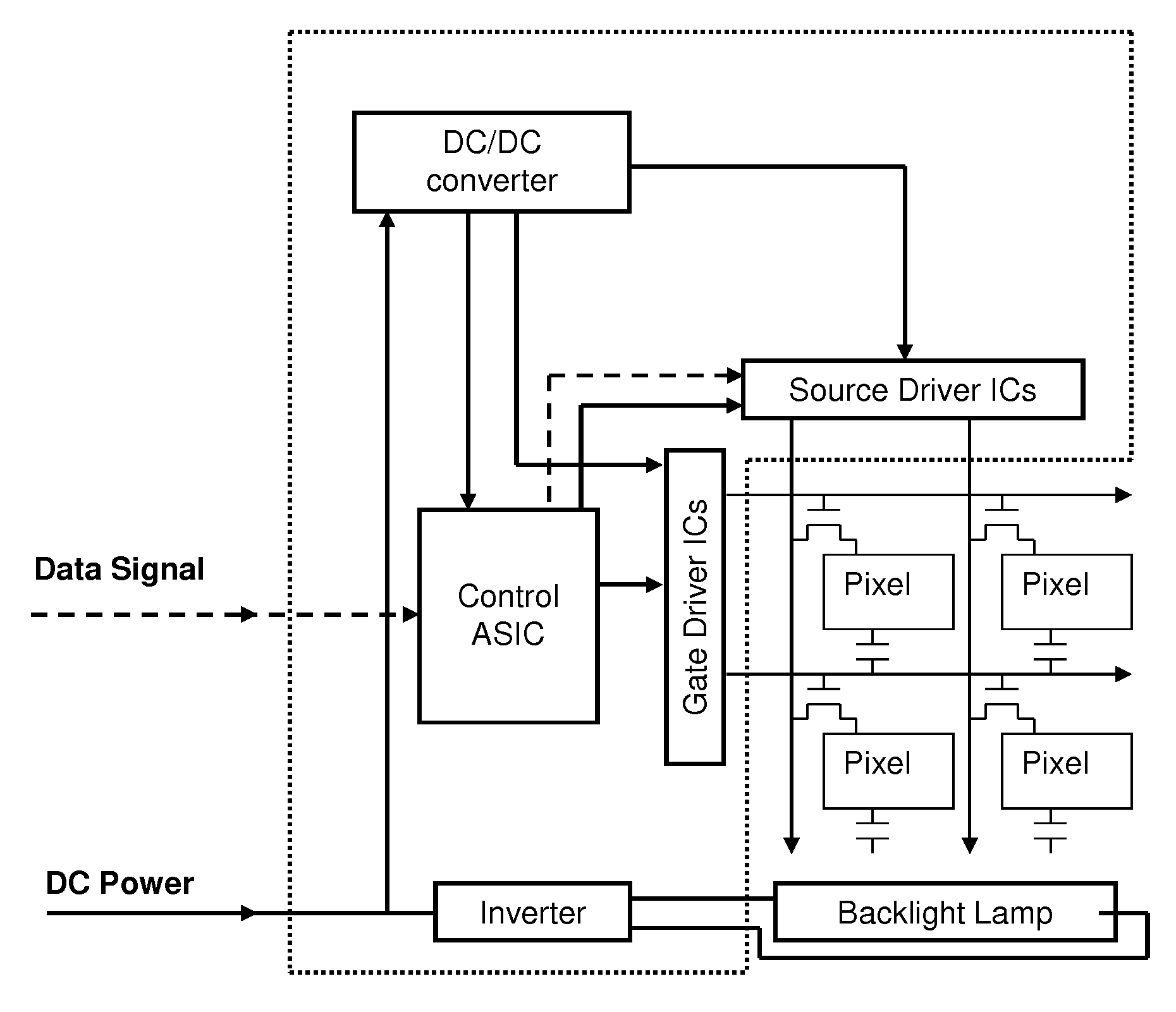
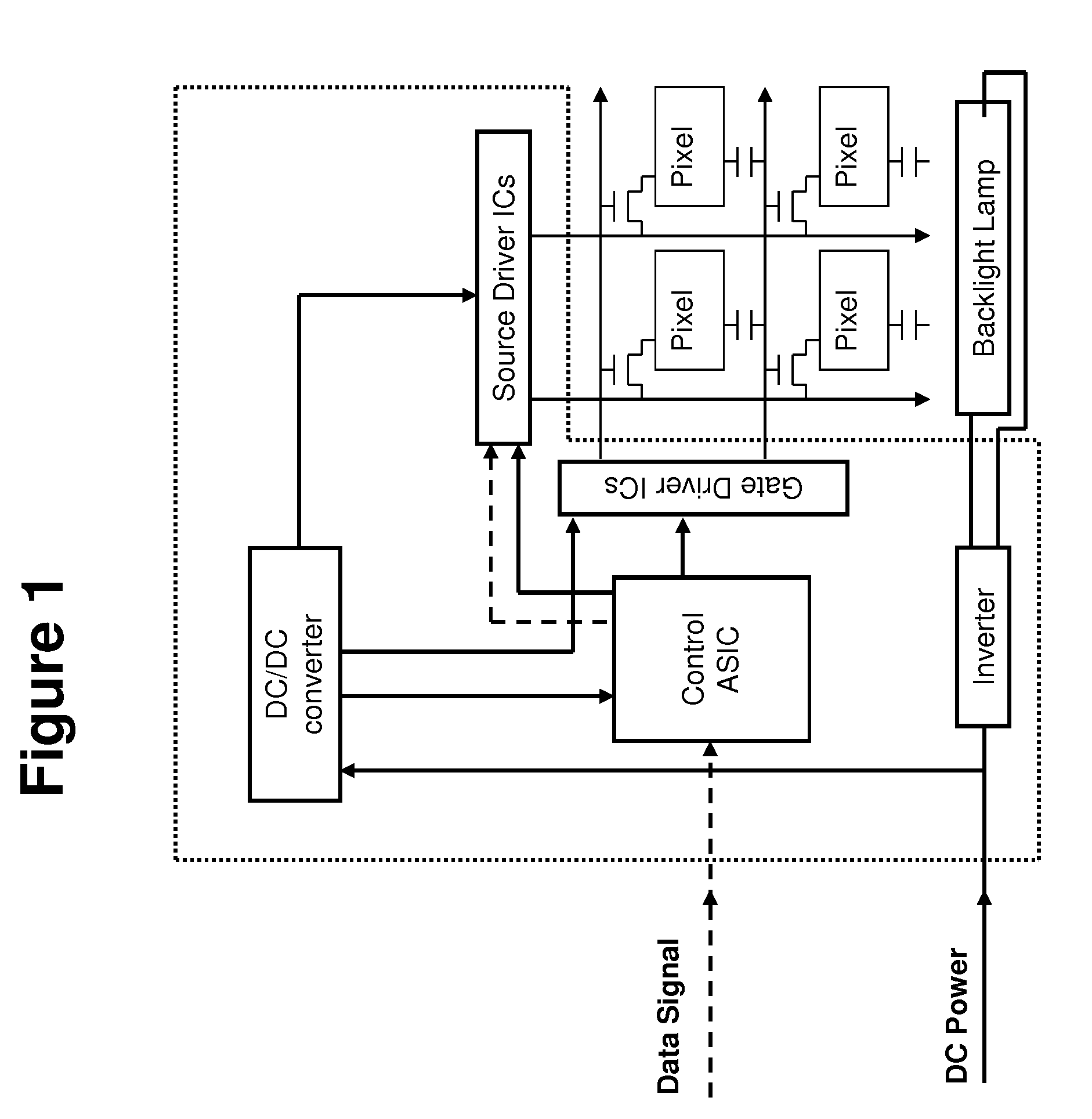
process flow diagram for performing the steps described above is given in FIG. 11. The process flow may be implemented via hardware,
software stored in computer-readable memory such as read-only memory or the like, or a combination thereof and may be implemented, for example, in the Control ASIC of the
control electronics represented in FIG. 1. Those having ordinary skill in the art of
computer software and / or hardware design for LCD displays will readily appreciate based on the description provided herein how to provide
software and / or hardware to carry out the functions described herein without undue effort or experimentation. Accordingly, further detail as to the particular arrangement has been omitted herein for the sake of brevity.
[0092]FIG. 11 exemplifies how initial RGB pixel data constituting an image is received by the Control ASIC, processed in accordance with the invention, and output as modified R′G′B′ pixel data. Specifically, the initial RGB data serves as indexing values to the plurality of LUTs discussed herein. The output values from each of the LUTs are input to a
multiplexer. The particular LUTs from which output values are selected are determined in part based on the output of a
Data Analysis block and Register block. The initial RGB data is analyzed by a
Data Analysis block in accordance with the analysis described herein so as to identify the top colour component having the highest
data level and the (h−m) value. The output of such analysis is provided to the selection input of the
multiplexer. The Register block stores the (h−m) threshold values as represented, for example, in FIG. 7. These threshold values are also provided to the selection input of the
multiplexer such that, in conjunction with the top colour component and (h−m) value, the corresponding LUT(s) which provide the modified R′G′B′ image data is selected. Within the selected LUT(s), which particular output value is selected is dependent on a
spatial parameter, also provided to a selection input of the multiplexer, based on the position of the pixel or sub-pixel being modified in the image to be displayed. The modified image data from the selected output of the selected LUT(s) is then provided to the source driver ICs and presented to each corresponding pixel.
[0093]It has been found that in the selection step, the h−m parameter provides a simple and
effective method of determining which LUT will provide the optimum reduction in colour shift when the modified values for the middle and lower colour component are retrieved from it. However, any other means of analysis of the input pixel values which provides the required differentiation between input colours requiring different output modifications to optimally reduce colour shift may be employed.

