Thin hollow backlights with beneficial design characteristics

a backlight and hollow technology, applied in the field of extended area light sources, can solve the problem of only modest reduction of brightness uniformity over the output area of such a backlight, and achieve the effect of small collective source area ratio and minimal loss of light sources

Inactive Publication Date: 2010-06-24
3M INNOVATIVE PROPERTIES CO
View PDF23 Cites 83 Cited by
  • Summary
  • Abstract
  • Description
  • Claims
  • Application Information

AI Technical Summary

Benefits of technology

[0020]Besides the front and back reflectors, highly reflective and low loss side reflectors are preferably provided to yield a substantially closed or sealed reflecting cavity, and losses associated with the light sources are kept to minimal levels by, fo

Problems solved by technology

The brightness uniformity over the output area of such a backlight is only modestly dimin

Method used


Image

  • Thin hollow backlights with beneficial design characteristics
  • Thin hollow backlights with beneficial design characteristics
  • Thin hollow backlights with beneficial design characteristics

Examples


example 21a

[0153]the output region of the Edge-Lit, Hollow Backlight was covered by a reflective polarizer (APF mounted on an acrylic plate) which was placed over the output area of the backlight. All of the LEDs (red, green, and blue, except for the single green LED mentioned above, for a total of 4R 7G 4B) were turned on to produce white light. The backlight was bright close to the LEDs and visibly darker at the far end (away from the LEDs).

example 21b

[0154]the same configuration as for Example 21a was used, but only the green LEDs were powered (except for the single green LED mentioned above, for a total of 7G). The backlight appeared much brighter close to the LEDs and darker at the far end (away from the LEDs).

example 21c

[0155]the same configuration as for Example 21a was used, but only the four green LEDs of the right bank of LEDs were powered (for a total of 4G). The backlight appeared much brighter on the right side close to the LEDs and was darker at the far end (away from the LEDs) and also darker on the left side where the LEDs weren't lit.


PUM


Abstract

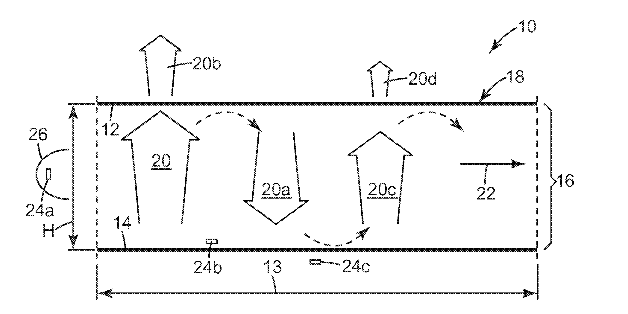
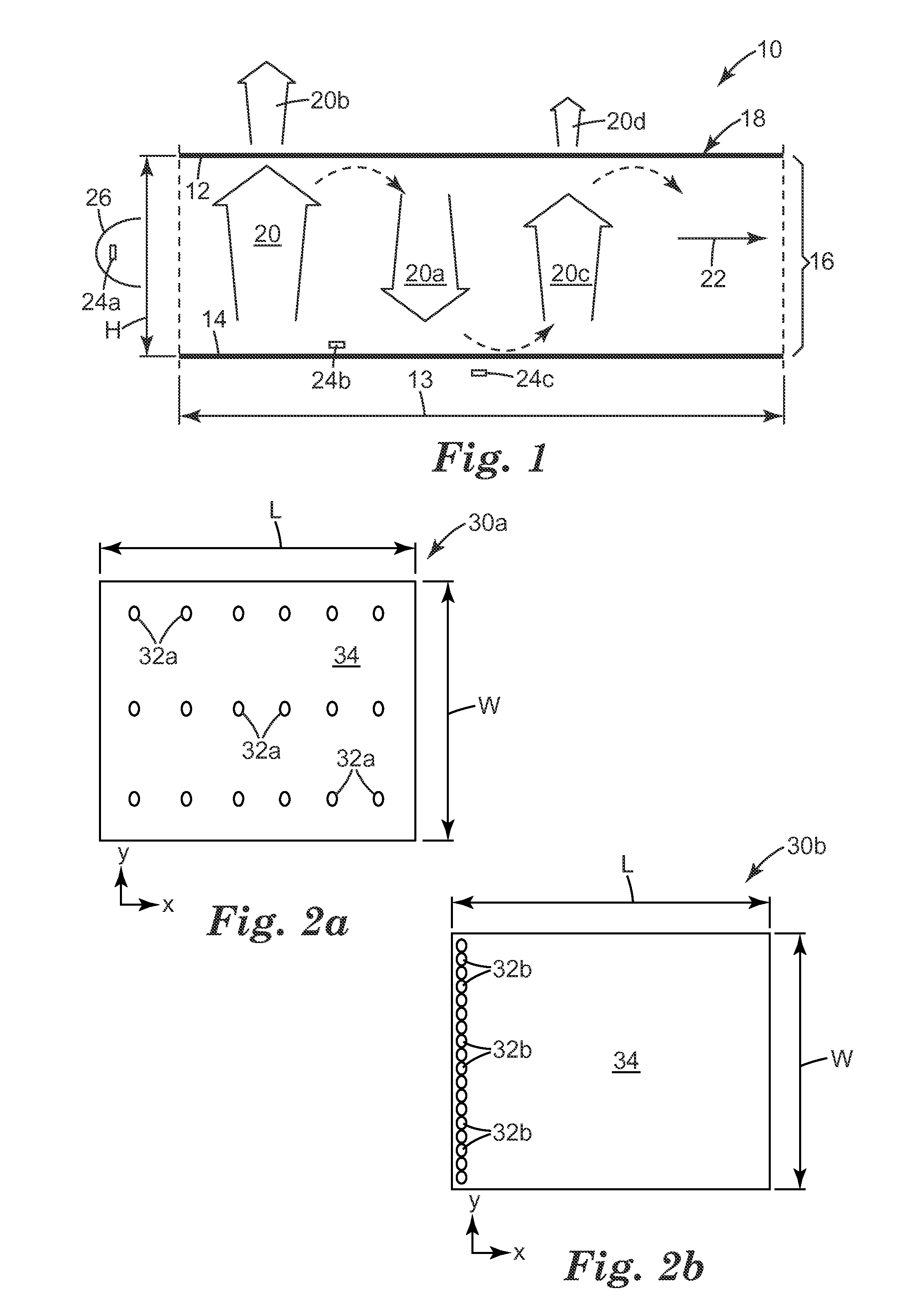
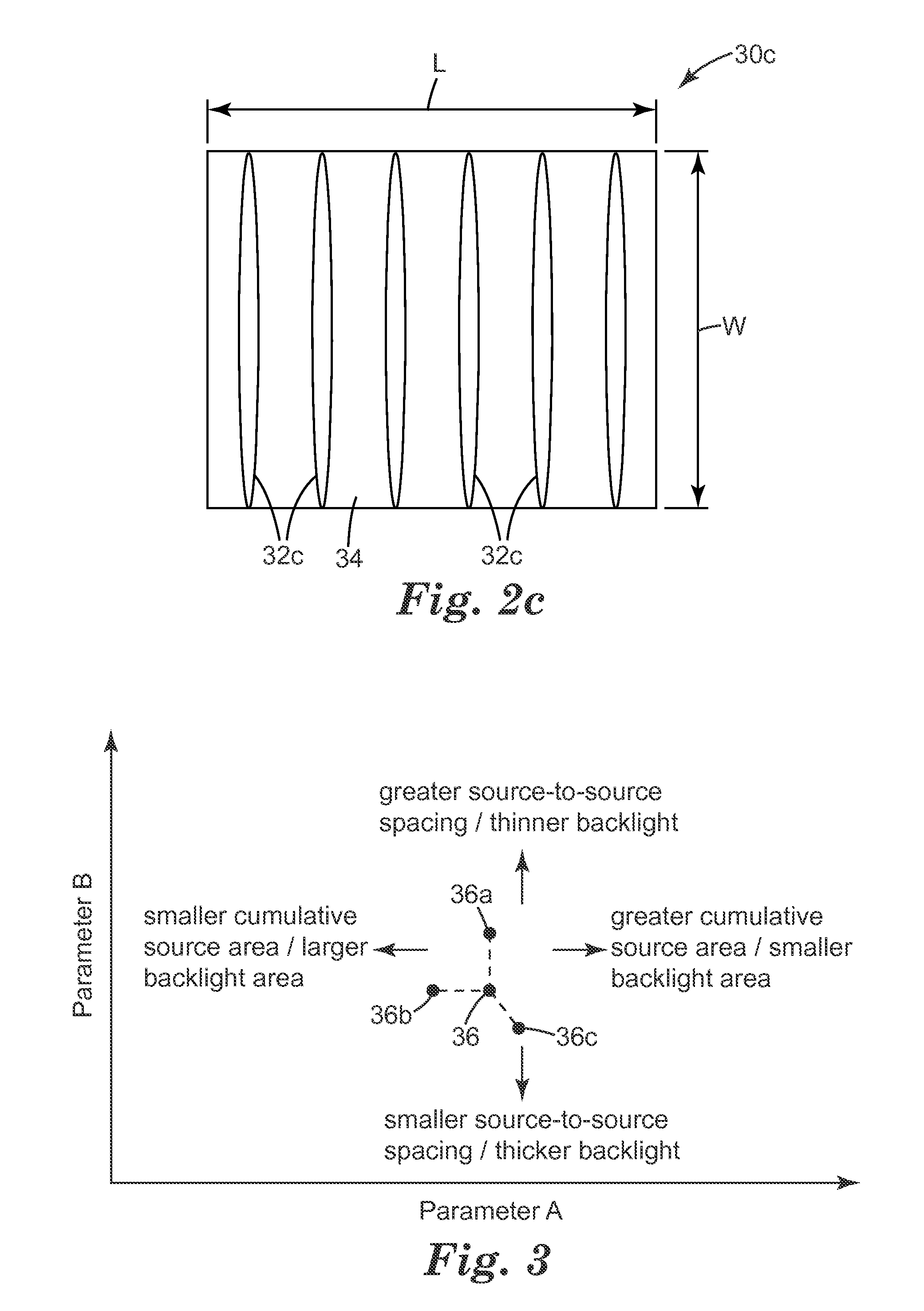
A backlight unit (10) has a hollow cavity (16) instead of employing a light guide. One or more light sources (24a-c), such as LEDs, are arranged to emit light into the cavity, which is formed by a front (12) and a back reflector (14). The backlight is typically of the edge-lit type. The backlight can have a large area, is thin and consists of fewer components than conventional devices. Its design permits light recycling. The unit emits light of a predefined polarisation and can be arranged to have desired horizontal/vertical viewing angle properties. Light is uniformly distributed within the guide and the light output (20b, 2Od) is substantially collimated. Such backlights occupy a specific region in a parameter space defined by two parameters: first, the ratio of the output emission area to the total source emission area should lie in the range 0.0001 to 0.1; and second, the ratio of the SEP to the height of the cavity (H) should be in the range 3 to 10, where the SEP is an average plan view source separation, a special measure of the average spacing of light sources in the plane of the unit. There is also a discussion on the required number of light sources N, their arrangement near the periphery of the cavity, as well as the shape and size of the output emission area. A required minimum brightness uniformity (VESA) value to be maintained, when a subset of Madjacent sources is switched off (where M is at least 0.1 N or M>2 or both), is also disclosed. The backlight can be used for a display or for general lighting purposes.

Description

RELATED APPLICATIONS[0001]The following co-owned and copending PCT Patent Applications are incorporated herein by reference: PCT Patent Application No. ______, entitled BACKLIGHT AND DISPLAY SYSTEM USING SAME (Attorney Docket No. 63274WO004); PCT Patent Application No. ______, entitled RECYCLING BACKLIGHTS WITH SEMI-SPECULAR COMPONENTS (Attorney Docket No. 63032WO003); PCT Patent Application No. ______, entitled WHITE LIGHT BACKLIGHTS AND THE LIKE WITH EFFICIENT UTILIZATION OF COLORED LED SOURCES (Attorney Docket No. 63033WO004); and PCT Patent Application No. ______, entitled COLLIMATING LIGHT INJECTORS FOR EDGE-LIT BACKLIGHTS (Attorney Docket No. 63034WO004).FIELD[0002]The present disclosure relates to extended area light sources suitable for illuminating a display or other graphic from behind, commonly referred to as backlights. The disclosure is particularly suited, but not necessarily limited, to backlights that emit visible light of substantially only one polarization state.BA...

Claims


Application Information

Patent Timeline
IPC IPC(8): G09G5/10
CPCG02B6/0055G02B6/0056G02B6/0068F21V7/04G02F1/133603G02F1/133605G02F1/13362G02B6/0096G02B6/00G02F1/1335
Inventor NEVITT, TIMOTHY J.HEBRINK, TIMOTHY J.WEBER, MICHAEL F.BIERNATH, ROLF W.FREIER, DAVID G.WHEATLEY, JOHN A.OUDERKIRK, ANDREW J.HOYLE, CHARLES D.DERKS, KRISTOPHER J.
Owner 3M INNOVATIVE PROPERTIES CO
Why Eureka
Try Eureka