Illumination apparatus, projector, and polarization conversion element
- Summary
- Abstract
- Description
- Claims
- Application Information
AI Technical Summary
Benefits of technology
Problems solved by technology
Method used
Image

Examples
first embodiment
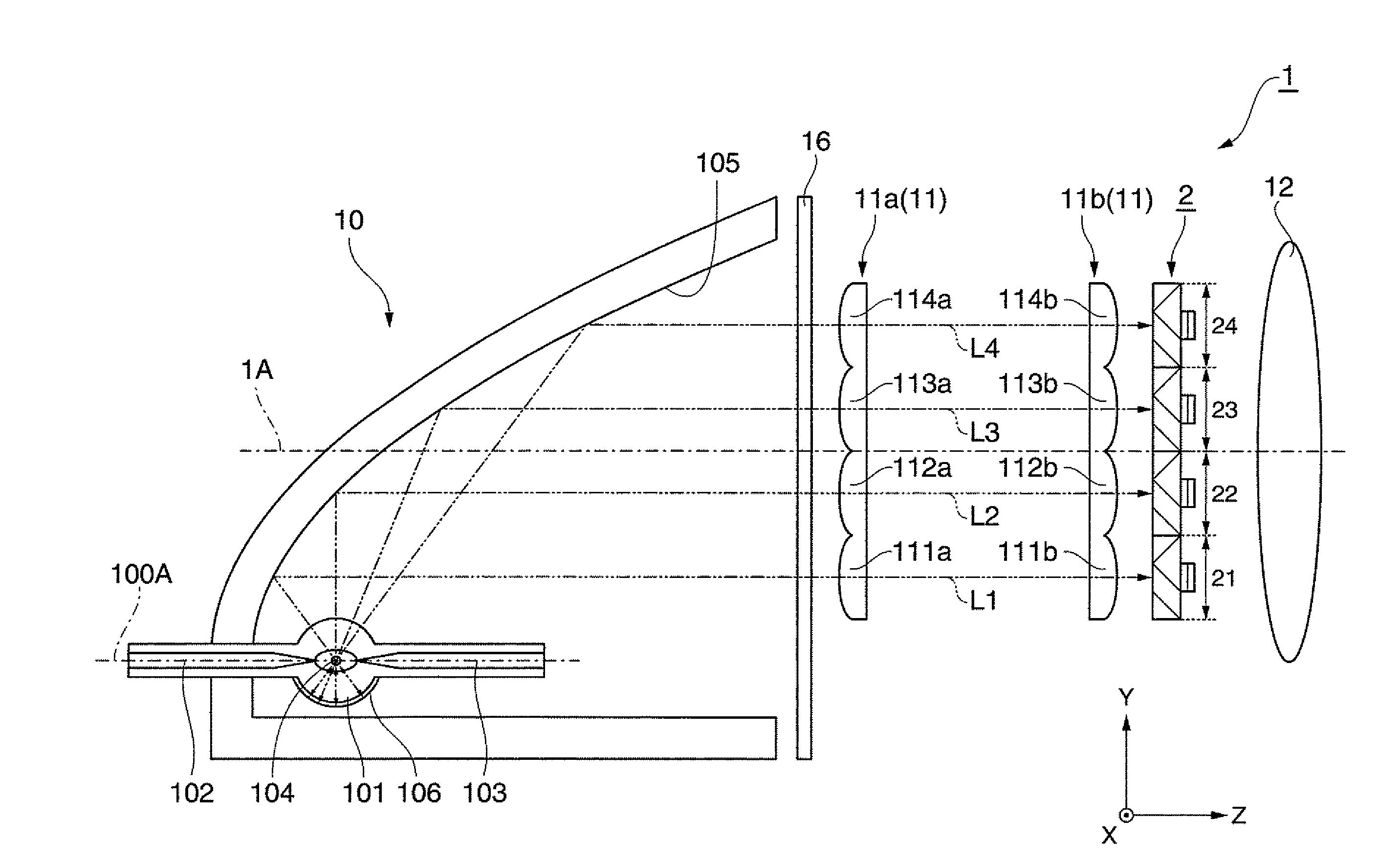
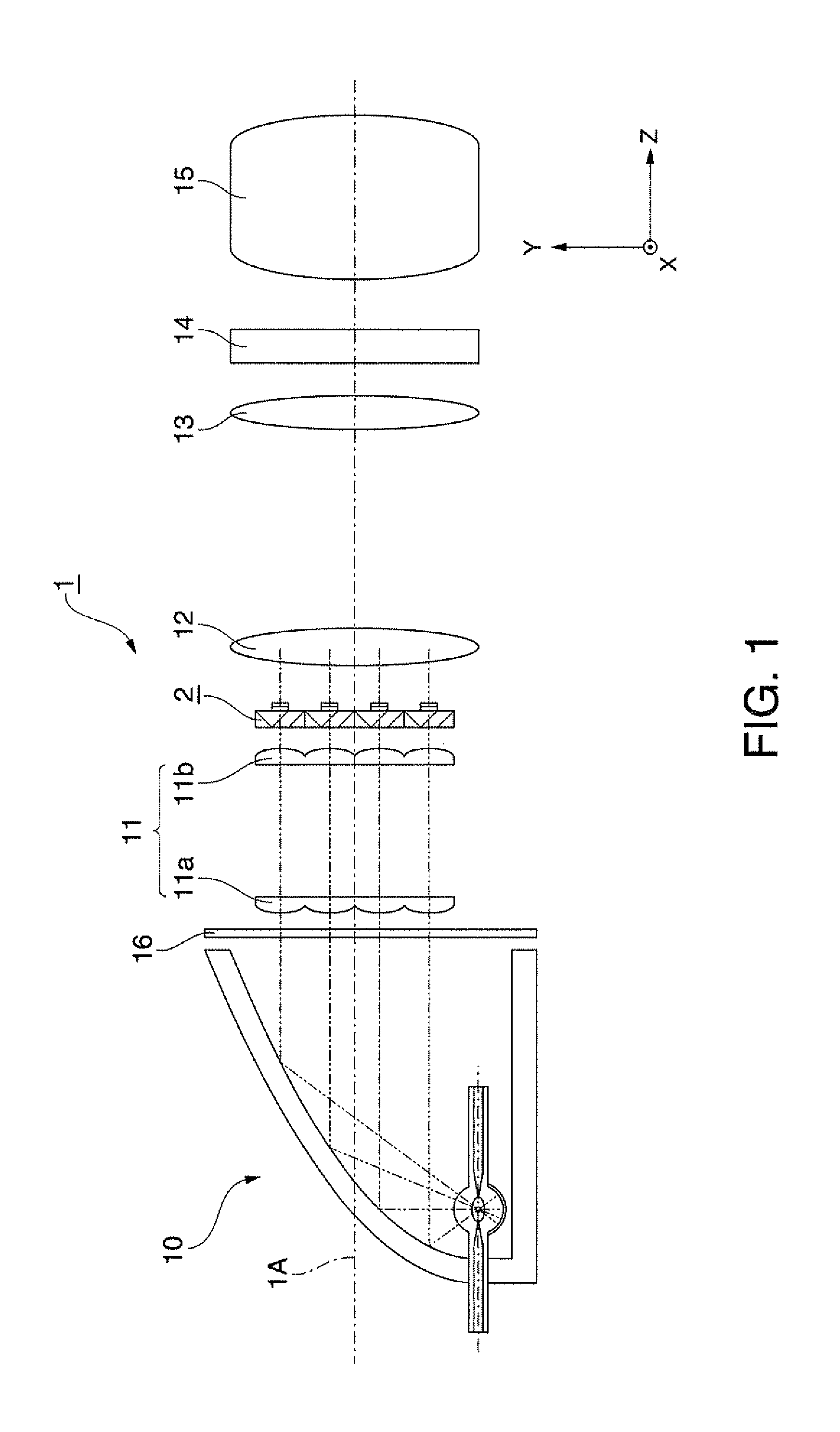
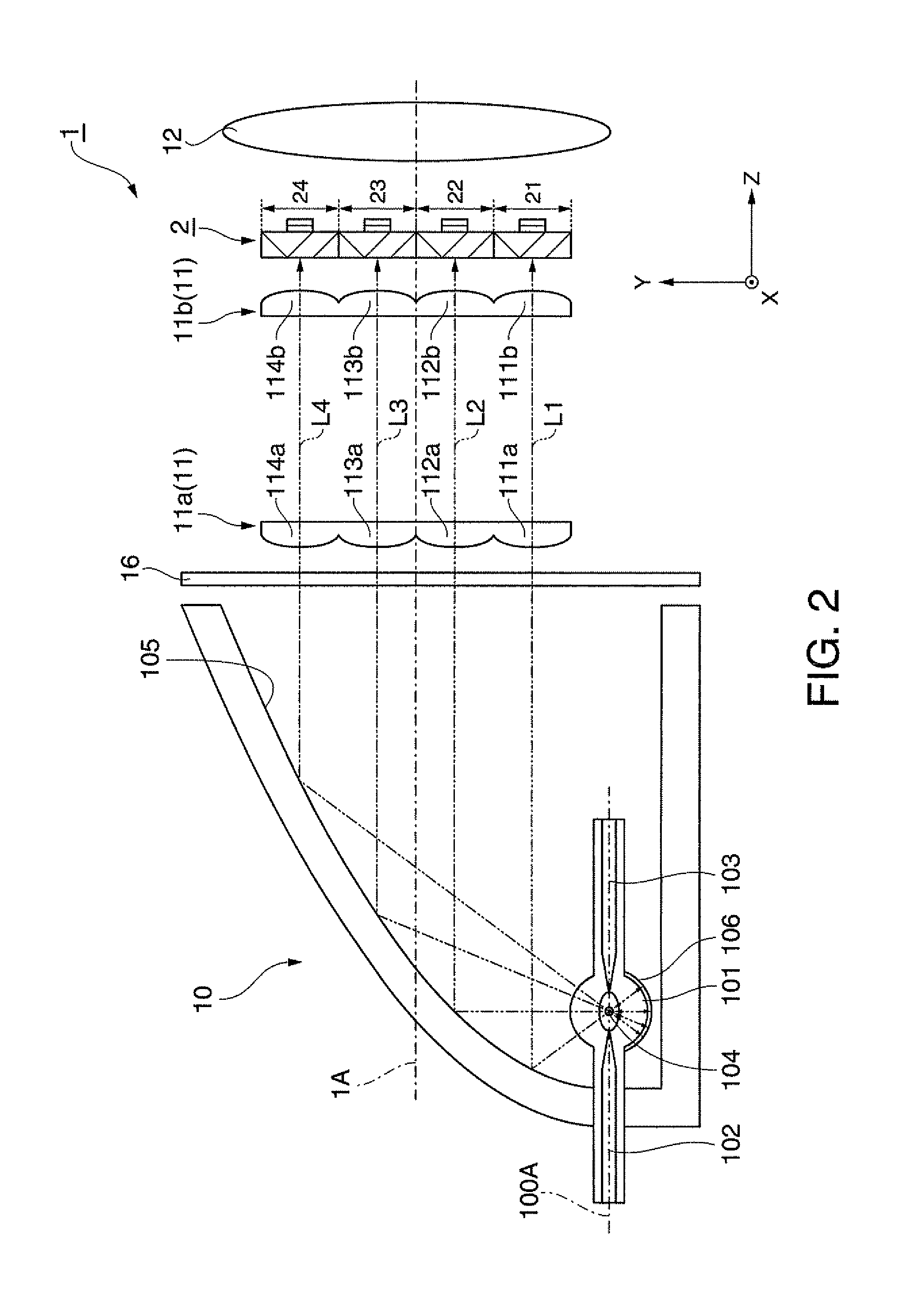
[0044]FIG. 1 is a schematic diagram showing a general configuration of an illumination apparatus 1 according to a first embodiment.
[0045]As shown in FIG. 1, the illumination apparatus 1 is provided with a light source device 10, an illuminance equalizing optical system (a converging optical system) 11, a polarization conversion element 2, and a condenser lens (an overlapping optical system) 12. An illumination light axis 1A as a light axis of the illumination apparatus 1 is substantially identical to a light axis of the light source device 10. The light source light emitted from the light source device 10 proceeds along the illumination light axis 1A, and illuminates an area to be illuminated (hereinafter referred to as an illuminated area) after passing through the illuminance equalizing optical system 11, a polarization conversion element 2, and the condenser lens 12 in this order.
[0046]In the present embodiment, it is arranged that the light emitted from the illumination apparatu...
second embodiment
[0094]Then, an illumination apparatus according to a second embodiment of the invention will be explained. The second embodiment is different from the first embodiment in that the illumination apparatus is configured with a polarization conversion element different from the polarization conversion element according to the invention.
[0095]FIG. 5A is a schematic diagram showing schematic configuration of the illumination apparatus 3 according to the second embodiment, and FIG. 5B is a schematic diagram enlargedly showing the polarization conversion element.
[0096]As shown in FIG. 5A, the illumination apparatus 3 is provided with a light source device 30, an illuminance equalizing optical system 31, a condenser lens 32, a polarization conversion element 33, and a filter 36. In the illumination apparatus 3, the constituents other than the polarization conversion element 33 are the same as those of the first embodiment. The light source light emitted from the light source device 30 procee...
third embodiment
[0103]Then, an illumination apparatus according to a third embodiment of the invention will be explained. The third embodiment is different from the first embodiment in that the first reflector is formed of a part of a spheroid, and that the polarization conversion element is formed of a single polarization conversion unit.
[0104]FIG. 6 is a schematic diagram showing a general configuration of an illumination apparatus 4 according to the third embodiment.
[0105]As shown in FIG. 6, the illumination apparatus 4 is provided with a light source device 40, a polarization conversion element 41, a condenser lens 42, a filter 46, and a collimating lens (a converging optical system) 47. The condenser lens 42 and the filter 46 are the same as those in the first embodiment.
[0106]The light source device 40 is mainly composed of a lamp light source and a reflector. The lamp light source is exactly the same as that of the first embodiment, and disposed so as to extend in a direction along the lamp ...
PUM
 Abstract
Description
Claims
Application Information