Method for identifying an abnormal disc

a technology of abnormal discs and optical drives, applied in the field of optical drives, can solve the problems of poor quality of focus spots of light beams, spherical aberration (sa), and uneven light beam luminance of projecting light beams, so as to improve signal quality and optimize light beam focus quality

Inactive Publication Date: 2010-06-24
QUANTA STORAGE INC
View PDF5 Cites 2 Cited by
  • Summary
  • Abstract
  • Description
  • Claims
  • Application Information

AI Technical Summary

Benefits of technology

[0010]The disclosure is also directed to a method for identifying an abnormal disc by using the SA value corresponding to the maximum focus error signal, which is obtained after abnormal disc is identified, to pre-calibrate the spherical aberration. Thus, the focus quality of the light beam may be optimized and the signal quality may be enhanced.

Problems solved by technology

As for a small optical device, there are difficulties in regulating its material, shaping, curved surface and smoothness during the manufacture process, with the result that the luminance of the projecting light beam is not uniform, and the spherical aberration (SA) tends to occur.
Thus, a focus spot of the light beam is presented with poor quality, which influences the correct reading for pits.
The disc substrates may have thickness variations because the disc substrates are inaccurately manufactured by different manufacturers with different manufacture processes.
As for the abnormal disc having thinner or thicker substrate, using the SA value set by the standard specification fails to focus the light beam with optimum quality.
Thus, in the servo system of the optical drive, the qualities of all signals are lowered, and the data read / write error or failure is presented.
Thus, the optical drive still has problems in identifying the abnormal disc.

Method used


Image

  • Method for identifying an abnormal disc
  • Method for identifying an abnormal disc
  • Method for identifying an abnormal disc

Examples


Embodiment Construction

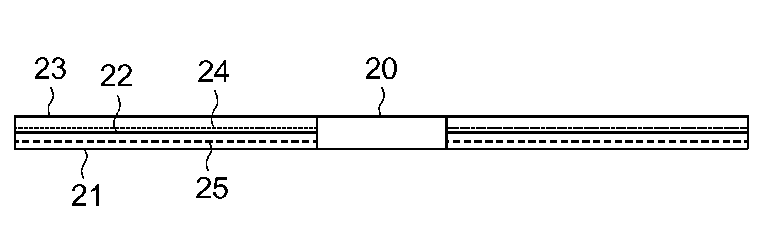
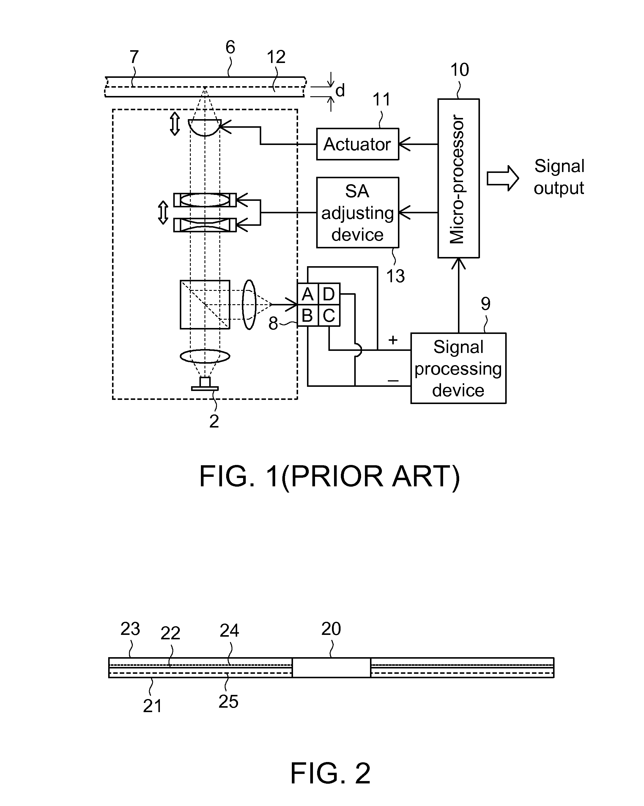
[0019]FIG. 2 is a schematically cross-sectional view showing a disc 20. As shown in FIG. 2, the disc 20 is formed by coating a data layer 22 on a bottom substrate 21, and then covering a protection layer 23 over the data layer 22. The data layer 22 has a standard position according to the specification of various discs 20. The data layer 22 is located at a specific position of the disc according to the thickness of the substrate 21 so that pits are formed to record the data. The method for identifying the abnormal disc according to the invention is performed according to the property of the standard position of the data layer 22. Because the typical optical drive performs test for the standard positions of the data layers 22 set by various specifications of the discs 20, and stores corresponding standard SA values such that the optimum signal quality may be maintained. If the substrate 21 is thicker, the position of its data layer 24 is higher than that of the standard data layer 22...


PUM

PropertyMeasurementUnit
smoothnessaaaaaaaaaa
luminanceaaaaaaaaaa
thicknessaaaaaaaaaa

Abstract

A method for identifying an abnormal disc includes the steps of: forming three testing spherical aberration (SA) values including an SA value of a thinner data layer, a standard SA value and an SA value of a thicker data layer; adjusting to one of the testing SA values; performing focus for a target disc and recording a focus error signal; obtaining a maximum focus error signal and a corresponding testing SA value by way of comparison; and checking whether the corresponding testing SA value is equal to the standard SA value, and identifying the target disc as a normal disc if yes, or otherwise identifying the target disc as the abnormal disc and re-adjusting the SA value to enhance the signal quality.

Description

[0001]This application claims the benefit of Taiwan application Serial No. 97150174, filed Dec. 22, 2008, the subject matter of which is incorporated herein by reference.BACKGROUND OF THE DISCLOSURE[0002]1. Technical Field[0003]The invention relates in general to a method for identifying an abnormal disc, and more particularly to a method of an optical drive for identifying an abnormal disc with a thinner or thicker disc substrate.[0004]2. Description of the Related Art[0005]An optical device, such as an objective lens, in an optical pick-up of an optical drive is relatively small. As for a small optical device, there are difficulties in regulating its material, shaping, curved surface and smoothness during the manufacture process, with the result that the luminance of the projecting light beam is not uniform, and the spherical aberration (SA) tends to occur. Thus, a focus spot of the light beam is presented with poor quality, which influences the correct reading for pits.[0006]FIG....

Claims


Application Information

Patent Timeline
Patent Type & Authority Applications(United States)
IPC IPC(8): G11B20/18
CPCG11B7/1392G11B2220/2537G11B20/1816
Inventor HSU, CHIA-HSINGCHEN, PEI-KANGHSIAO, YI-LONG
Owner QUANTA STORAGE INC
Why Eureka
Try Eureka