Tactile Pin Display Apparatus

a display apparatus and tactile pin technology, applied in the field of can solve the problems of inability to automatically return the tactile pin, difficulty in maintaining the tactile pin in the off-state, and the inability to rotate stationary, so as to reduce the size, weight and cost of the tactile pin display apparatus, and ensure the linkage of the cam.

Inactive Publication Date: 2010-06-24
ASKK
View PDF3 Cites 17 Cited by
  • Summary
  • Abstract
  • Description
  • Claims
  • Application Information

AI Technical Summary

Benefits of technology

[0008]This structure in the tactile pin display apparatus of the present invention allows the cams in the ON-state to support the tactile pins, and prevents ends of the tactile pins from being lowered back to the OFF-state from the ON-state even if the tactile pins are pressed by a finger of a user with a large force of about 1 N (newton) to 10 N. This eliminates the need for a holding current to maintain the tactile pins, making it possible to achieve energy reduction. In addition, all the tactile pins can be instantaneously and automatically lowered back to near the tactile surface, namely can be instantaneously brought to the OFF-state, by a single reciprocal movement of the cam return plate and by the spring force of the springs to continuously bias the tactile pins against the cams. These make it possible to achieve the simplification and reduction of the tactile pin display apparatus in size, weight and cost.
[0009]Preferably, the shape memory wires are heated by current through conducting brushes. Further preferably, the tactile pin display apparatus further comprises wire support fittings integrally provided on the cams for pinching the shape memory wires, wherein the conducting brushes are elastically contacted with the wire support fittings so as to heat the shape memory wires by current through the wire support fittings. This makes it possible to securely link the cams to the shape memory wires, and to lower the conduction resistance to the shape memory wires, and thereby to securely and stably supply power to the shape memory wires.
[0010]Further, the cam return member driving source preferably comprises a motor, in which the cam return member is reciprocated by rotation of the motor. Otherwise, the cam return member driving source preferably comprises a solenoid, in which the cam return member is reciprocated by ON / OFF operation of the solenoid. This makes it possible to securely lower the ends of the tactile pins in the ON-state to near the tactile surface.

Problems solved by technology

However, the shape memory wire is non-conducting in the ON-state of the tactile pin, so that if the rotation-axial center of the cam is significantly far from the axial center in the lengthwise direction of the tactile pin, the cam cannot fix and support the tactile pin, because a rotational moment is exerted on the cam, resulting in a rotation of the cam, when the tactile pin is pressed by a finger with a force of 0.1 N to 0.3 N for tactile, even if the tactile pin in the ON-state rides on the cam surface.
However, the setting of such supporting force means that it is difficult to stably maintain the tactile pin in the OFF-state.
Accordingly, there is a risk that in the ON-state, the cam which should be stationary may be forced to rotate.
Thus, it was not possible to allow the tactile pin to automatically return to the OFF-state by using e.g. a compression coil spring.
Accordingly, a process is necessary to touch newly displayed tactile pins (braille) after once using a finger to press and reset all the tactile pins in the ON-state to the OFF-state, resulting in an extremely complicated tactile operation.
This is also a big obstacle when continuously displaying the tactile pins (braille).
Thus, there is a risk that this may cause an unstable contact resistance.
Note that also in FIG. 1 and FIG. 2 of the same Patent Publication showing a tactile pin display apparatus which does not use a spring, it is presumed difficult to place the tactile pins at narrow intervals of 2.5 mm to 3 mm, making it difficult to form a tactile pin display apparatus for braille display of multiple rows and multiple columns.

Method used


Image

  • Tactile Pin Display Apparatus
  • Tactile Pin Display Apparatus
  • Tactile Pin Display Apparatus

Examples


Embodiment Construction

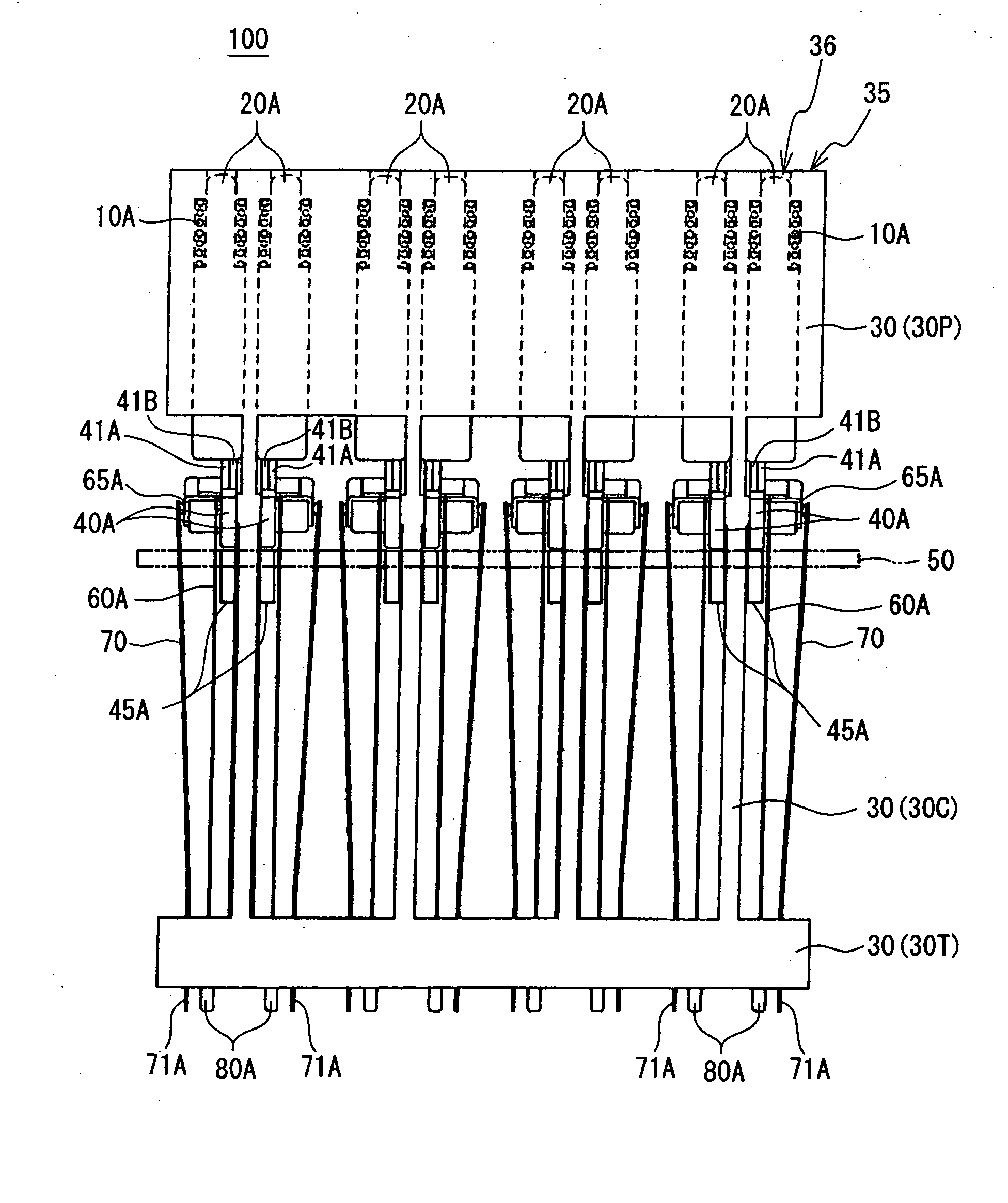
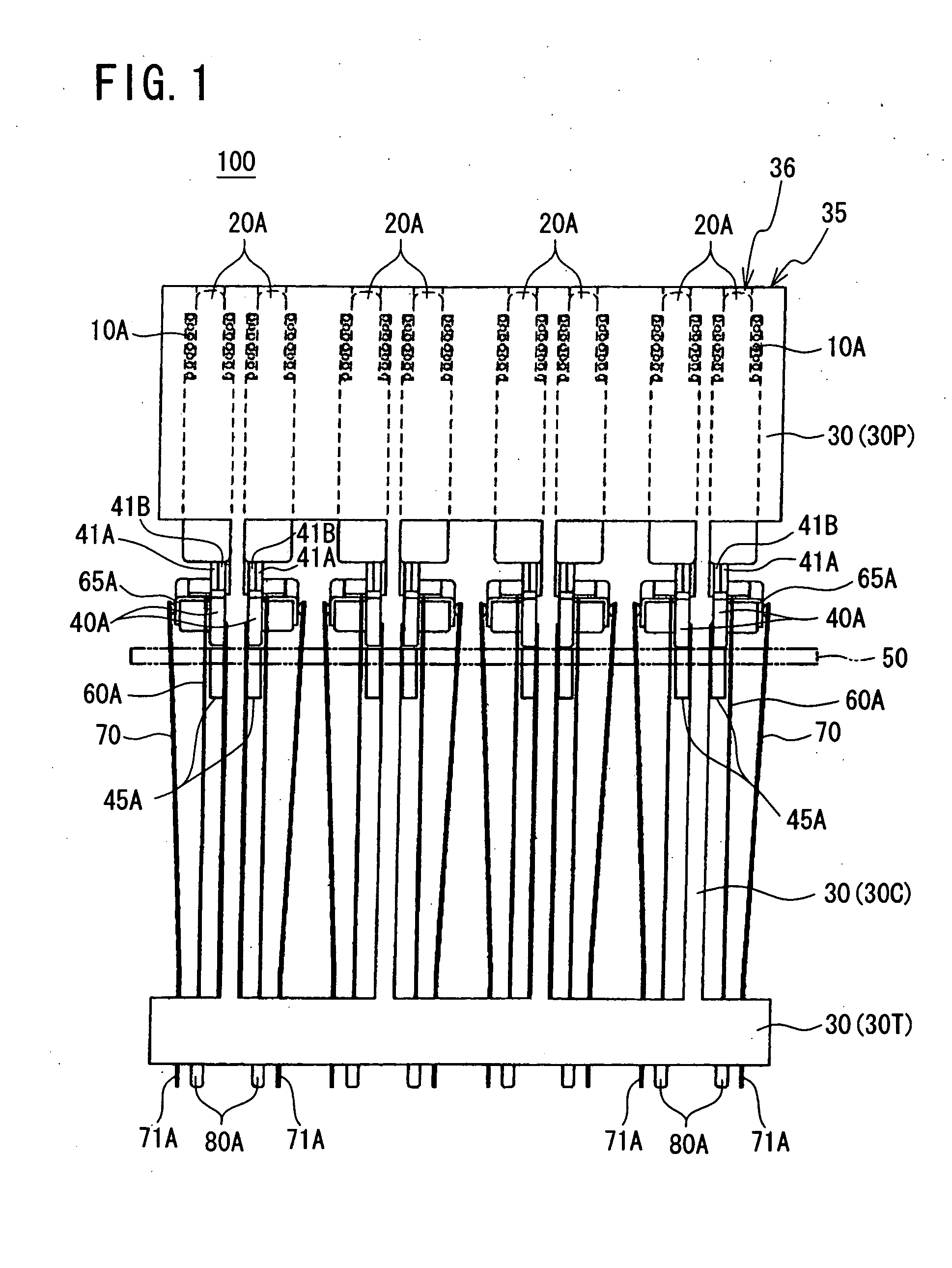
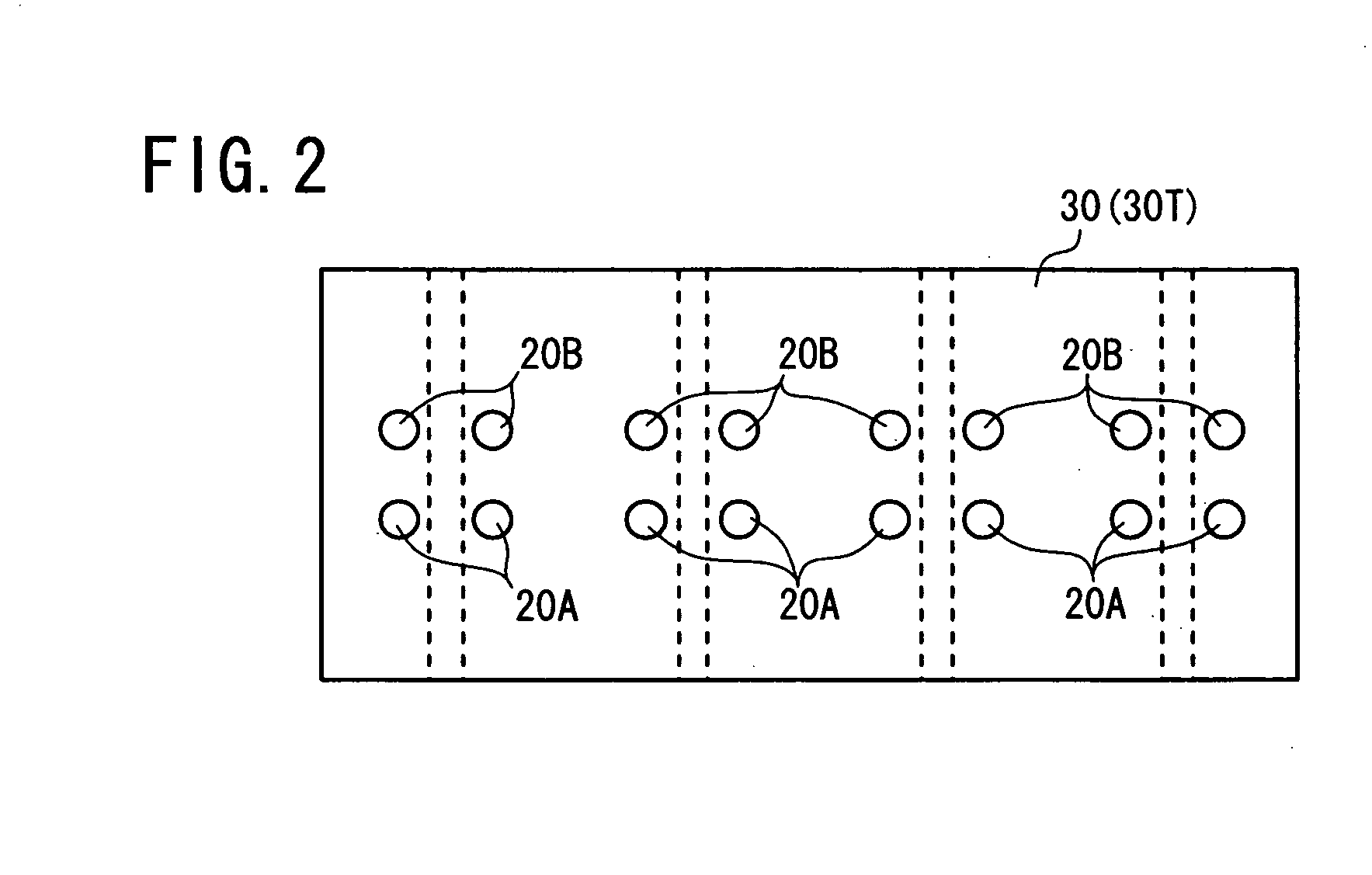
[0020]FIG. 1 is a schematic front view of a tactile pin display apparatus 100 according to an embodiment of the present invention, while FIG. 2 is a schematic plan view of the tactile pin display apparatus 100. The tactile pin display apparatus 100 can display four digit braille numbers, and is formed of eight tactile pin display units 200 described later (using two tactile pins 20A, 20B) arranged in a row at predetermined intervals. Thus, a first row of eight tactile pins 20A and a second row of eight tactile pins 20B are formed. Suffixes A and B are added to elements accompanied by the first and second tactile pins 20A and 20B, respectively, while these suffixes are not added to elements common to the first row and second row. FIG. 1 is a front view of the tactile pin units 200 arranged in a row as seen from the side of the first row.

[0021]Referring to FIG. 1 and FIG. 2, reference numeral 20A (20B) denotes stepped tactile pins made of stainless steel, and 40A (40B) denotes cams ma...


PUM


Abstract

A tactile pin display apparatus comprises: tactile pins 20 for braille display; a support housing 30 for supporting and allowing the tactile pins 20 to move forward and backward; cams 40 for raising ends of the tactile pins 20 to a desired height (ON-state) from a tactile surface 35; compression coil springs 10 for biasing the tactile pins 20 against the cams 40; shape memory wires 60 to be heated by current for pivoting the cams 40 forward to bring the tactile pins to the ON-state; and a cam return plate 50 for pivoting the cams backward to lower the tactile pins 20 back to a level (OFF-state) of the tactile surface 35. Even if in the ON-state the tactile pins 20 are strongly pressed by a user, or the current to the shape memory wires 60 is disconnected, the tactile pins 20 are not lowered back because upper surfaces of the cams 40 support lower surfaces of the tactile pins 20. All the tactile pins 20 can be lowered back to the OFF-state by a single reciprocal movement of the cam return plate 50.

Description

TECHNICAL FIELD[0001]The present invention relates to a tactile pin display apparatus for displaying braille numbers formed of substantially semi-spherical projections (or tactile pins) of multiple dots (e.g. four dots), or arbitrary braille characters formed of substantially semi-spherical projections (or tactile pins) of multiple dots (e.g. six or eight dots), or arbitrary braille graphics. More specifically, it relates to a tactile pin display apparatus which uses cams and shape memory wires to raise ends of tactile pins to a desired height (“ON” state) from a tactile surface.BACKGROUND ART[0002]A conventional tactile pin (braille) display apparatus arranges, into one line of character string for display, a predetermined number of braille display members (braille display units) which electromechanically raise ends of multiple tactile pins (braille pins) for braille display. A visually handicapped person slides a finger on the line for tactile (reading) so as to transfer informati...

Claims


Application Information

Patent Timeline
Patent Type & Authority Applications(United States)
IPC IPC(8): G09B21/00
CPCG09B21/004G06F3/016G06F3/01G09B21/003G06F3/02G09B21/00
Inventor HASHIZUME, MICHINORIKAJINO, JIROSHIMIZU, KAORUASAO, TOMOHIRO
Owner ASKK
Why Eureka
Try Eureka