Implantable optical glucose sensing

a technology of optical glucose sensing and implantable sensors, applied in the field of implantable sensors, can solve the problems of cell death, affect the exchange of substances between cells and their environment,

Inactive Publication Date: 2010-06-24
GLUSENSE LTD
View PDF98 Cites 37 Cited by
  • Summary
  • Abstract
  • Description
  • Claims
  • Application Information

AI Technical Summary

Problems solved by technology

Fibrotic overgrowth around the implanted cells, however, gradually impairs substance exchange between the cells and their environment.
Hypoxia of the cells typically leads to cell death.

Method used


Image

  • Implantable optical glucose sensing
  • Implantable optical glucose sensing
  • Implantable optical glucose sensing

Examples


Embodiment Construction

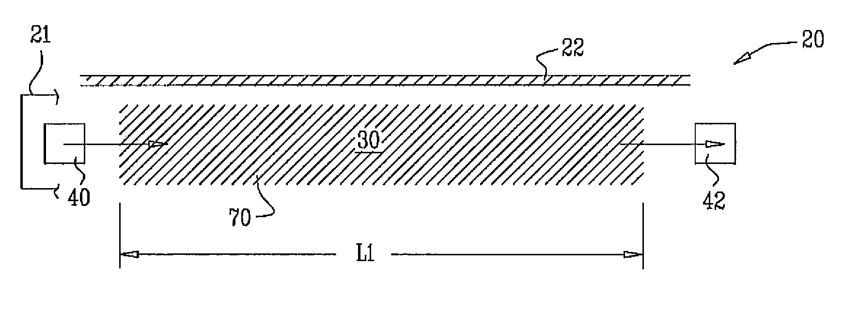
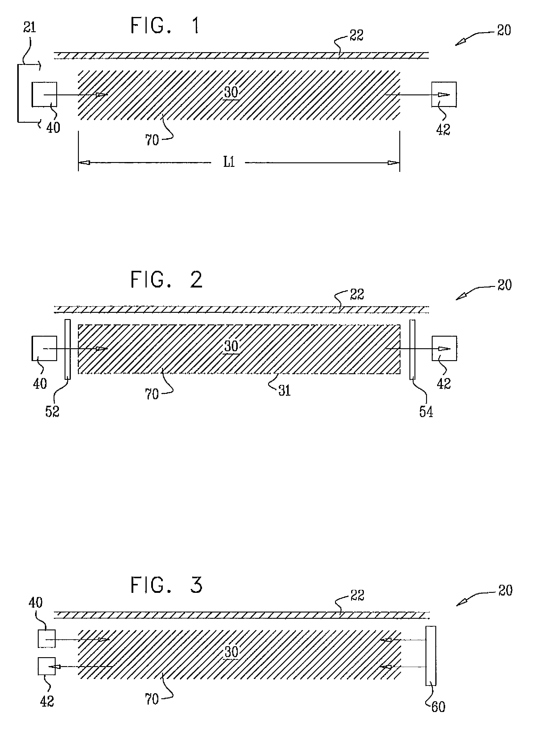
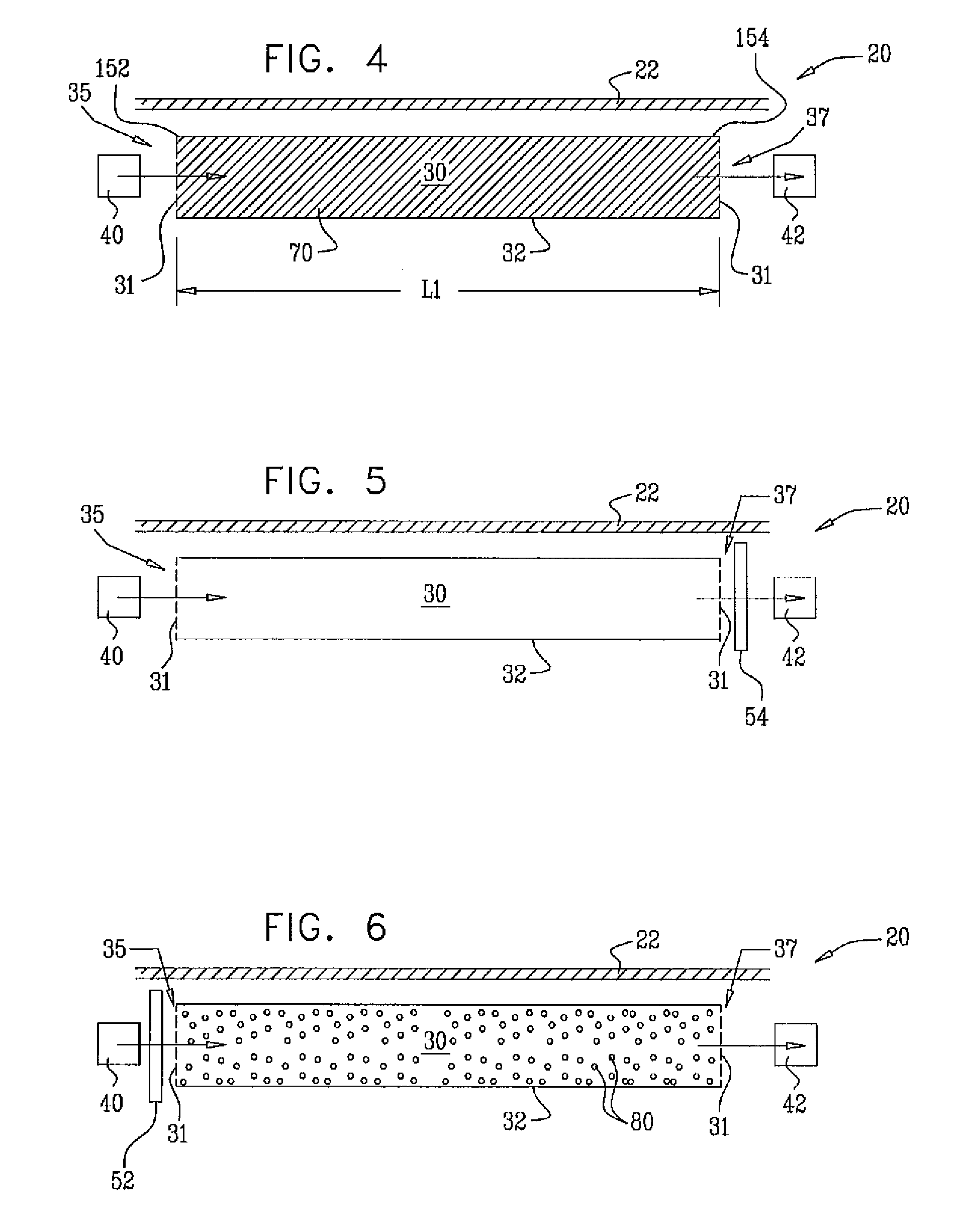
[0186]Reference is now made to FIG. 1, which is a schematic illustration of an optical measuring device 20 comprising an electromagnetic light source 40 and a detecting system 42, in accordance with an embodiment of the present invention. Typically, light source 40 is configured to emit electromagnetic radiation that is in the visible or infrared range. Optical measuring device 20 is configured to detect and measure a concentration of an analyte, e.g., glucose, in interstitial fluid of a subject. (In the context of the specification, examples of the analyte being glucose are by way of illustration and not limitation.) Typically, device 20 is designated for subcutaneous implantation under skin 22 of a subject. Typically, device 20 comprises a support 21 (e.g., a housing, a scaffold, or glue). A sampling region 30 is disposed within an area defined by support 21 of device 20, typically between light source 40 and detecting system 42 (as shown). Support 21 is configured to facilitate p...


PUM


Abstract

Apparatus is provided, including a support configured to be implanted within a body of a subject and a sampling region coupled to the support. The apparatus is configured to passively allow passage through the sampling region of at least a portion of fluid from the subject. The apparatus also comprises an optical measuring device in optical communication with the sampling region. The optical measuring device comprises at least one light source configured to transmit light through at least a portion of the fluid, and at least one sensor configured to measure a parameter of the fluid by detecting light passing through the fluid. Other embodiments are also described.

Description

CROSS-REFERENCES TO RELATED APPLICATIONS[0001]The present application is related to:[0002]U.S. Provisional Patent Application 60 / 588,211 to Gross et al., entitled, “Implantable sensor,” filed Jul. 14, 2004;[0003]U.S. Provisional Patent Application 60 / 658,716 to Gross et al., entitled, “Implantable fuel cell,” filed Mar. 3, 2005;[0004]PCT Patent Application PCT / IL2005 / 000743 to Gross et al., entitled “Implantable power sources and sensors,” filed Jul. 13, 2005;[0005]U.S. Provisional Patent Application 60 / 786,532 to Gross et al., entitled, “Implantable sensor,” filed Mar. 28, 2006;[0006]PCT Patent Application PCT / IL2007 / 000399 to Gross, entitled “Implantable sensor,” filed Mar. 28, 2007.[0007]All of these applications are incorporated herein by reference.FIELD OF THE INVENTION[0008]The present invention relates generally to implantable sensors and specifically to methods and apparatus for sensing blood glucose concentrations.BACKGROUND OF THE INVENTION[0009]Diabetes mellitus is a dise...

Claims


Application Information

Patent Timeline
Patent Type & Authority Applications(United States)
IPC IPC(8): A61B5/1459
CPCA61B5/14532A61B5/6846A61B5/1459A61B5/14558
Inventor GROSS, YOSSIHYMAN, TEHILAGIL, TAMIR
Owner GLUSENSE LTD
Why Eureka
Try Eureka