Controller for internal combustion engine

a controller and internal combustion technology, applied in the direction of electric control, machines/engines, instruments, etc., can solve the problems of delayed difficult control difficult stabilization of the combustion condition, so as to achieve effective stabilization of the self-ignition combustion condition

Active Publication Date: 2010-06-24
DENSO CORP
View PDF5 Cites 19 Cited by
  • Summary
  • Abstract
  • Description
  • Claims
  • Application Information

AI Technical Summary

Benefits of technology

[0006]The present invention is made in view of the above matters, and it is an object of the present invention to provide a controller which can stabilize the self-ignited combustion condition effectively.
[0008]According to the above configuration, in the self-ignited combustion region, the valve timing is controlled in such a manner as to establish a negative valve overlap period where the exhaust valve and the intake valve are closed at least in a posterior half of an exhaust stroke. During the negative valve overlap period, since a high temperature combustion gas remaining in the cylinder is compressed by a piston in the posterior half of the exhaust stroke, the temperature and pressure in the cylinder are increased.
[0009]During the negative valve overlap period, the fuel-reform injection is performed so that the fuel is injected into the cylinder. The fuel injected into the cylinder for the reform is exposed to high temperature and high pressure. Thus, a preliminary reaction of the combustion is started and the fuel is reformed to a condition where the self-ignition is easily performed.
[0012]The reform degree of the fuel injected by the fuel-reform injection is detected, and the fuel injection quantity of the output-control injection is corrected based on the reform degree of the fuel. Thereby, the self-ignited combustion condition detected in the present combustion cycle is estimated according to the reform degree of the fuel injected by the fuel-reform injection in the present combustion cycle. Based on the estimated self-ignited combustion condition, the fuel injection quantity of the output-control injection is corrected to control the self-ignited combustion condition, so that the self-ignited combustion condition is stabilized.

Problems solved by technology

Generally, in the self-ignited combustion, a combustion condition control is difficult and a stabilization of combustion condition is hard, compared with a spark-ignited combustion.
Thus, it is likely that the control of the combustion condition is delayed and the self-ignited combustion can not be stabilized sufficiently.

Method used


Image

  • Controller for internal combustion engine
  • Controller for internal combustion engine
  • Controller for internal combustion engine

Examples


first embodiment

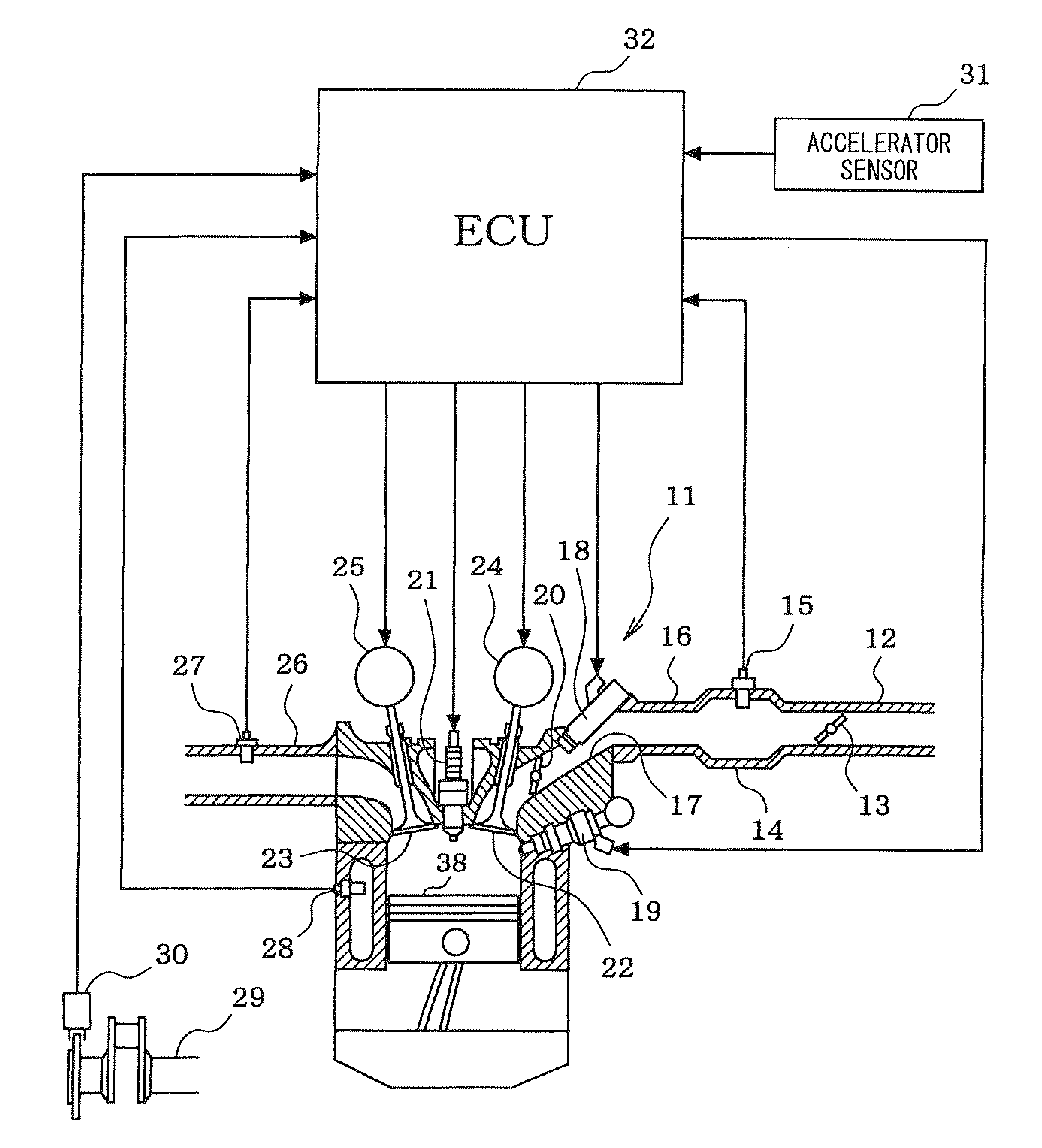
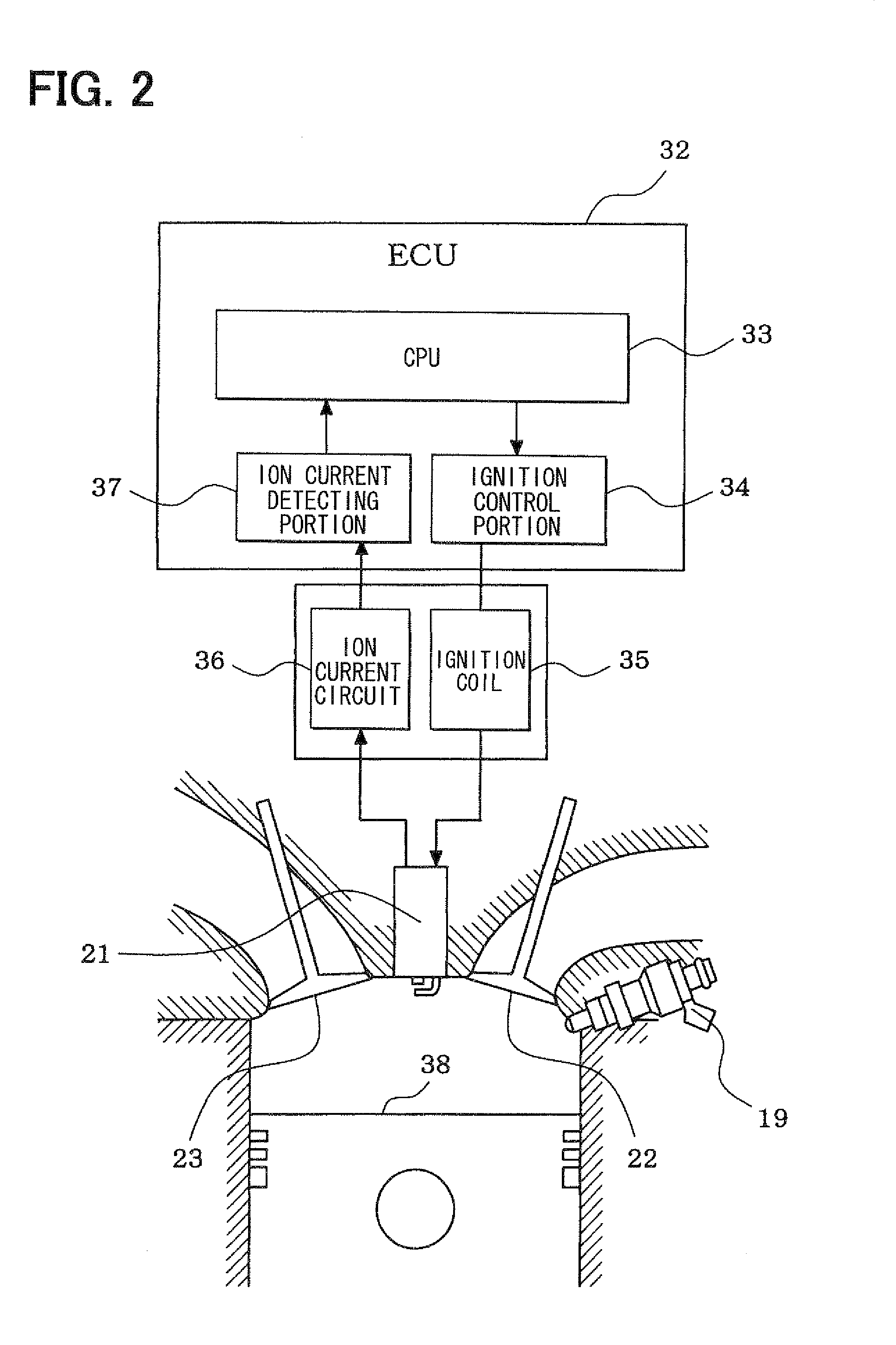
[0028]Referring to FIGS. 1 to 7, a first embodiment will be described hereinafter. Referring to FIG. 1, an engine control system is explained. An intake pipe 12 of an internal combustion engine 11 is provided with a throttle valve 13 which is driven by a motor (not shown). A surge tank 14 is provided downstream of the throttle valve 13. A pressure sensor 15 detecting an intake air pressure is disposed in the surge tank 14. An intake manifold 16 which introduces air into each cylinder of the engine 11 is connected to the surge tank 14.

[0029]The engine 11 is provided with a fuel injector 18 for an intake port injection and a fuel injector 19 for a direct injection. The fuel injector 18 injects the fuel into the intake port 17, and the fuel injector 19 injects the fuel into a cylinder directly. An air flow control valve 20 is disposed at each of the intake port 17 in order to control an air flow intensity (an intensity of swirl flow and an intensity of tumble flow) in each cylinder. A ...

second embodiment

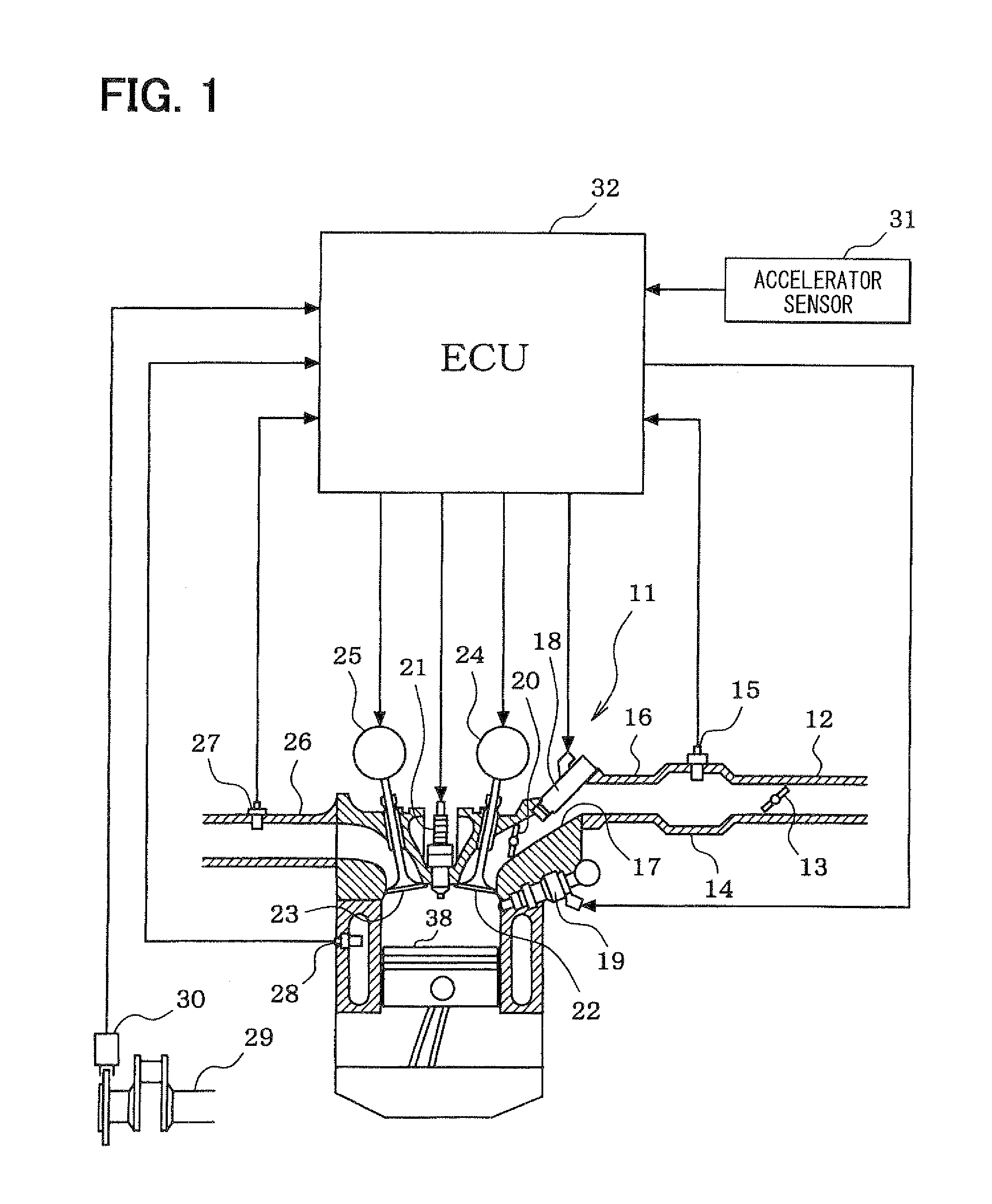
[0060]Referring to FIGS. 8 to 10, a second embodiment will be described hereinafter. As to the same parts and components as those in the first embodiment, the same descriptions will not be reiterated.

[0061]As shown in FIG. 8, since the ion quantity generated in the cylinder according to the combustion condition is varied to vary the ion-current, the ion-current is information which represents the combustion condition accurately. According to the second embodiment, the ion-current generated in accordance with the combustion condition of the air-fuel ratio is detected through the terminals of the spark plug 21. The integrated value (absolute value) of the ion-current signal is used as the information representing the combustion condition. In this case, according as the combustion becomes rapid, the ion quantity is increased and the integrated value of the ion-current signal becomes large. According as the combustion becomes slow, the ion quantity is decreased and the integrated value ...


PUM


Abstract

When a driving region of an engine is in a specified self-ignited combustion region, a valve timing is controlled in such a manner as to establish a negative valve overlap period in which an exhaust valve and an intake valve are closed. During the negative valve overlap period, a direct injection is performed to reform a fuel. After the direct injection, a port injection is performed to control an output. Thereby, a self-ignited combustion control is performed. During the self-ignited combustion control, a fuel reform degree of the fuel injected by the direct fuel injection is detected, and a self-ignited combustion condition in a present combustion cycle is estimated based on the fuel reform degree detected in the present combustion cycle. A fuel injection quantity of the intake port fuel injection is corrected according to the estimated self-ignited combustion condition in order to stabilize the self-ignited combustion condition.

Description

CROSS-REFERENCE TO RELATED APPLICATION[0001]This application is based on Japanese Patent Application No. 2008-327736 filed on Dec. 24, 2008, the disclosure of which is incorporated herein by reference.FIELD OF THE INVENTION[0002]The present invention relates to a controller for an internal combustion engine provided with a function in which air-fuel mixture is self-ignited to be combusted by compressing the air-fuel mixture during a compression stroke in a specified self-ignited combustion region.BACKGROUND OF THE INVENTION[0003]In order to reduce fuel consumption and a NOx emission, JP-2007-16777A (U.S. Pat. No. 7,210,457B2) and JP-2008-69788A (U.S. Pat. No. 6,994,073B2) show that an internal combustion engine is driven by a self-ignited combustion in which the air-fuel mixture is self-ignited to be combusted. Generally, in the self-ignited combustion, a combustion condition control is difficult and a stabilization of combustion condition is hard, compared with a spark-ignited comb...

Claims


Application Information

Patent Timeline
Patent Type & Authority Applications(United States)
IPC IPC(8): F02D43/00F01L1/34
CPCF02B23/104Y02T10/36F02D13/0215F02D13/0265F02D35/021F02D41/0025F02D41/3047F02D41/3094F02D2041/001F02D2200/0612Y02T10/123F02D19/061F02D19/0671F02D19/0689Y02T10/18F02B2275/16Y02T10/12Y02T10/30
Inventor SHIGENAGA, MASAHIROSAITOH, KIMITAKABASAKI, MASATOSHIWATANABE, KIYOHIKOMIWA, MAKOTO
Owner DENSO CORP
Why Eureka
Try Eureka