Steam turbine test facility, low-load test method, and load dump test method

a steam turbine and test facility technology, applied in the direction of engine testing, jet-propulsion engine testing, structural/machine measurement, etc., can solve the problems of unsteady steam flow inside the steam turbine, the test steam turbine cannot maintain its rotational speed by itself, and generate random vibration on the steam turbine, so as to improve the efficiency of performance and reliability verification

Active Publication Date: 2010-07-01
MITSUBISHI POWER LTD
View PDF9 Cites 19 Cited by
  • Summary
  • Abstract
  • Description
  • Claims
  • Application Information

AI Technical Summary

Benefits of technology

[0019]According to the present invention, it is possible to provide a steam turbine test facility including a test steam turbine, in which the behavior of an actual steam turbine can be precisely simulated particularly in the load dump test and the efficiency of tests for performance and reliability verification can be improved.

Problems solved by technology

When the load (steam flow rate) on the steam turbine falls to a fixed value or below and the steam turbine has long rotor blades (for example, in the case of a low-pressure turbine), a steam vortex flow may develop on the downstream side thereof, thereby generating random vibration on the steam turbine.
In the low-load test, if the power obtained by steam falls below mechanical loss, the test steam turbine cannot maintain its rotational speed by itself.
When the load on the steam turbine is disconnected, the pressure in the steam turbine suddenly decreases to cause the steam extracted from the main steam to flow reversely (flashback), thereby generating an unsteady steam flow inside the steam turbine.
A fluid force resulting from this unsteady steam flow creates an exciting force and thus flashback vibration occurs on the rotor blades.
Further, as proved in recent years, when the main steam is interrupted, the steam turbine enters an extremely low load state, the steam vortex flow generates random vibration, and the random vibration is superimposed on flashback vibration, with the result that a large vibration force occurs on the rotor blades.
However, it is known that in the load dump test, immediately after the load is disconnected (that is, the generator load is disconnected), the rotational speed of the actual steam turbine temporarily rises (overspeed).
Even when a drive turbine and a motor are connected to the test steam turbine so as to maintain the rotational speed with the load disconnected (that is, in a load disconnection state), it is not possible to precisely simulate transitional changes of the rotational speed of the actual steam turbine.
Specifically, with the conventional test steam turbine to which a common drive turbine and a motor are connected, it is not possible to precisely simulate the behavior appearing when the load on the actual steam turbine is disconnected.
Therefore, with the conventional test steam turbine, it is not possible to accurately evaluate an influence of flashback vibration and random vibration generated when the load is disconnected.
This will decrease the efficiency of tests for performance and reliability verification, inclusive of the above tests.

Method used


Image

  • Steam turbine test facility, low-load test method, and load dump test method
  • Steam turbine test facility, low-load test method, and load dump test method
  • Steam turbine test facility, low-load test method, and load dump test method

Examples


Embodiment Construction

[0023]Embodiments of the present invention will be described in detail below with reference to the accompanying drawings.

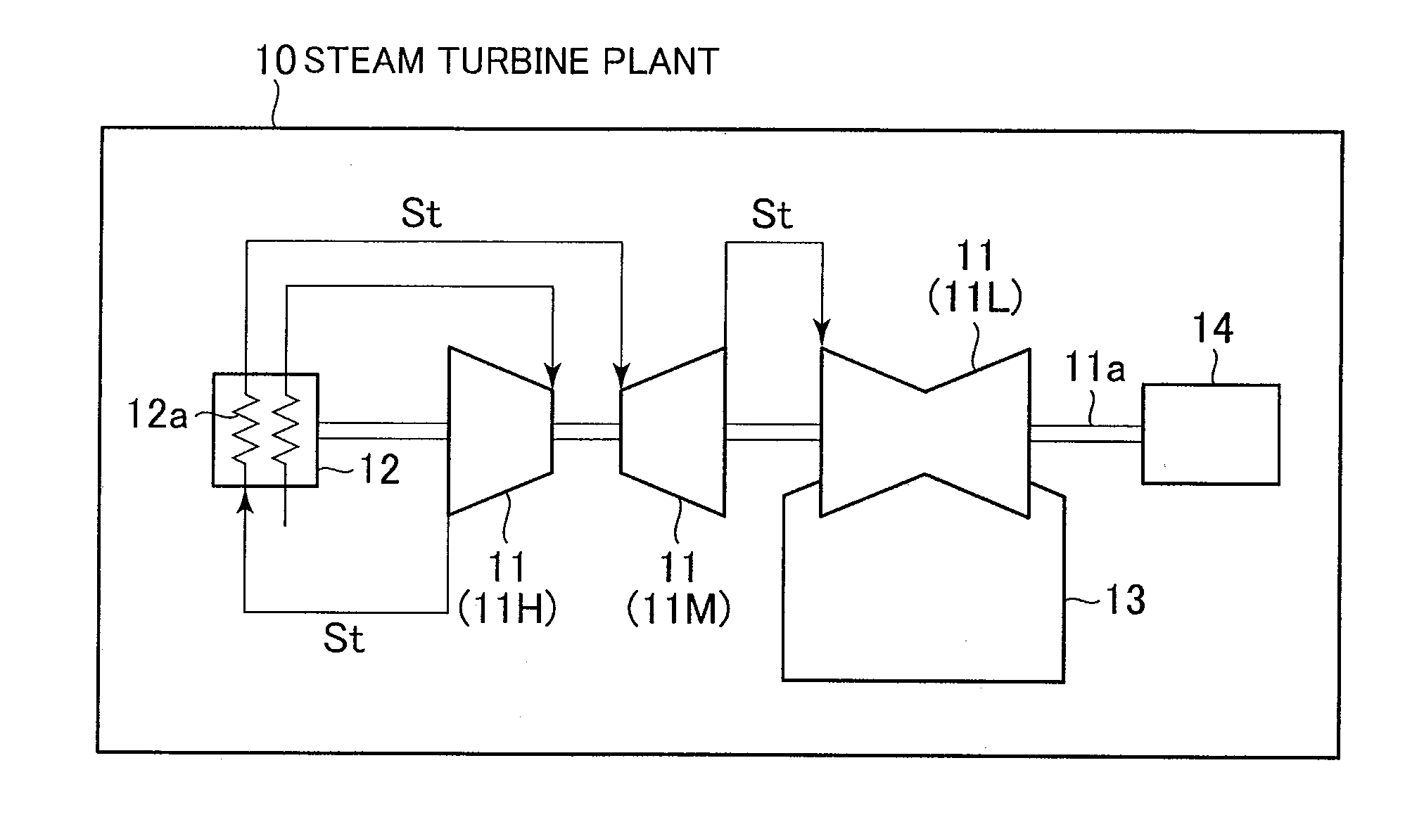
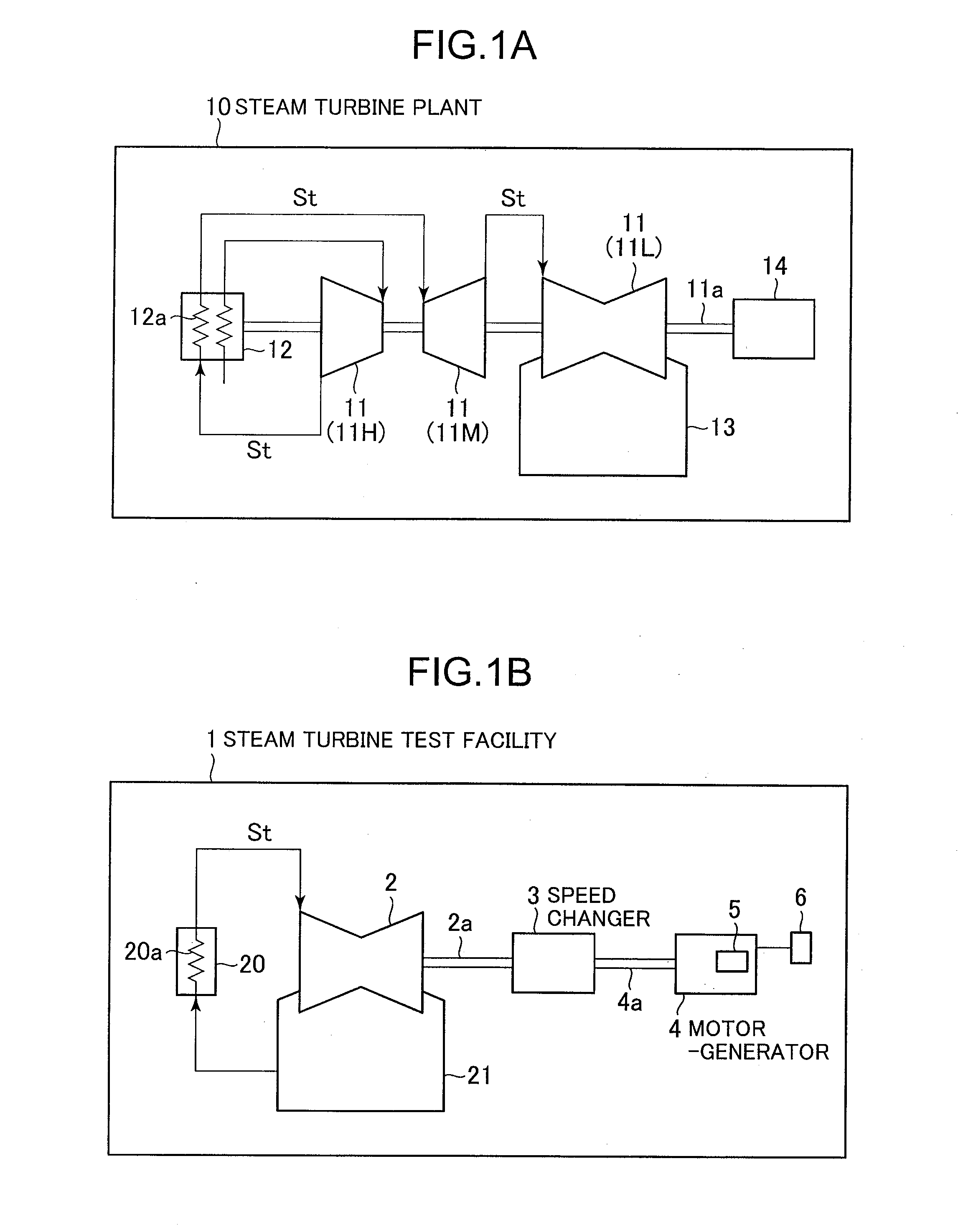
[0024]FIG. 1A illustrates a configuration of a common steam turbine plant, and FIG. 1B illustrates an exemplary configuration of a steam turbine test facility.

[0025]As illustrated in FIG. 1A, a common steam turbine plant 10 includes a high-pressure turbine 11H, a medium-pressure turbine 11M, and a low-pressure turbine 11L, as real steam turbines (steam turbines 11). In the thus-configured steam turbine plant 10, steam St generated by a boiler 12 generates work in the high-pressure turbine 11H, flows into a reheater 12a included in the boiler 12 for reheating, and flows into the medium-pressure turbine 11M. The steam St generates work in the medium-pressure turbine 11M, flows into the low-pressure turbine 11L, generates work in the low-pressure turbine 11L, and flows into a condenser 13. When the steam St generates work in the high-pressure turbine 11H, the medium-...


PUM


Abstract

It is an object of the present invention to provide a steam turbine test facility including a test steam turbine, in which the behavior of an actual steam turbine can be precisely simulated and the efficiency of performance test can be improved. A steam turbine test facility 1 includes a test steam turbine 2 which simulates the behavior of a real steam turbines 11 included in the steam turbine plant 10, and a motor-generator 4 connected to the test steam turbine 2. A control unit 5 included in the motor-generator 4 controls the motor-generator 4 to change the rotational speed of the test steam turbine 2 based on an arbitrarily set speed change pattern. The speed change pattern is set such that the test steam turbine 2 in the load disconnection state simulates a time-profile of the rotational speed of the steam turbines 11 with the load disconnected.

Description

BACKGROUND OF THE INVENTION[0001]1. Field of the Invention[0002]The present invention relates to a steam turbine test facility for performing tests for performance and reliability verification of a steam turbine plant, a low-load test method using the steam turbine test facility, and a load dump test method using the same.[0003]2. Description of the Related Art[0004]Conventionally, a steam turbine test facility is provided to evaluate the performance of a steam turbine plant constituting a part of a thermal power plant or a nuclear power plant. Such a steam turbine test facility includes a test steam turbine. The test steam turbine is used to simulate the behavior of a steam turbine installed in the steam turbine plant in such a manner that any particular one of a high-pressure turbine, a medium-pressure turbine, and a low-pressure turbine of the steam turbine plant is operated on a simulation basis. The steam turbine test facility performs performance and reliability verification t...

Claims


Application Information

Patent Timeline
Patent Type & Authority Applications(United States)
IPC IPC(8): G01M15/14G01M99/00
CPCG01M15/14
Inventor NAKAMURA, TATEKIKUDO, TAKESHISHIBASHITA, NAOAKI
Owner MITSUBISHI POWER LTD
Why Eureka
Try Eureka