Apparatus and methods for inspecting and cleaning subsea flex joints

a technology for flex joints and apparatus, which is applied in the field of subsea interventions, can solve the problems of extreme load conditions on the riser assembly and mooring system components, damage to and/or failure of the stress joint connecting the riser assembly to the subsea equipment, and complex simultaneous translation and rotational motion of the platform, so as to improve the remote inspection and/or cleaning, enhance the inspection and cleaning operation, and improve the effect of cleaning power

Active Publication Date: 2010-07-01
BP CORP NORTH AMERICA INC
View PDF21 Cites 6 Cited by
  • Summary
  • Abstract
  • Description
  • Claims
  • Application Information

AI Technical Summary

Benefits of technology

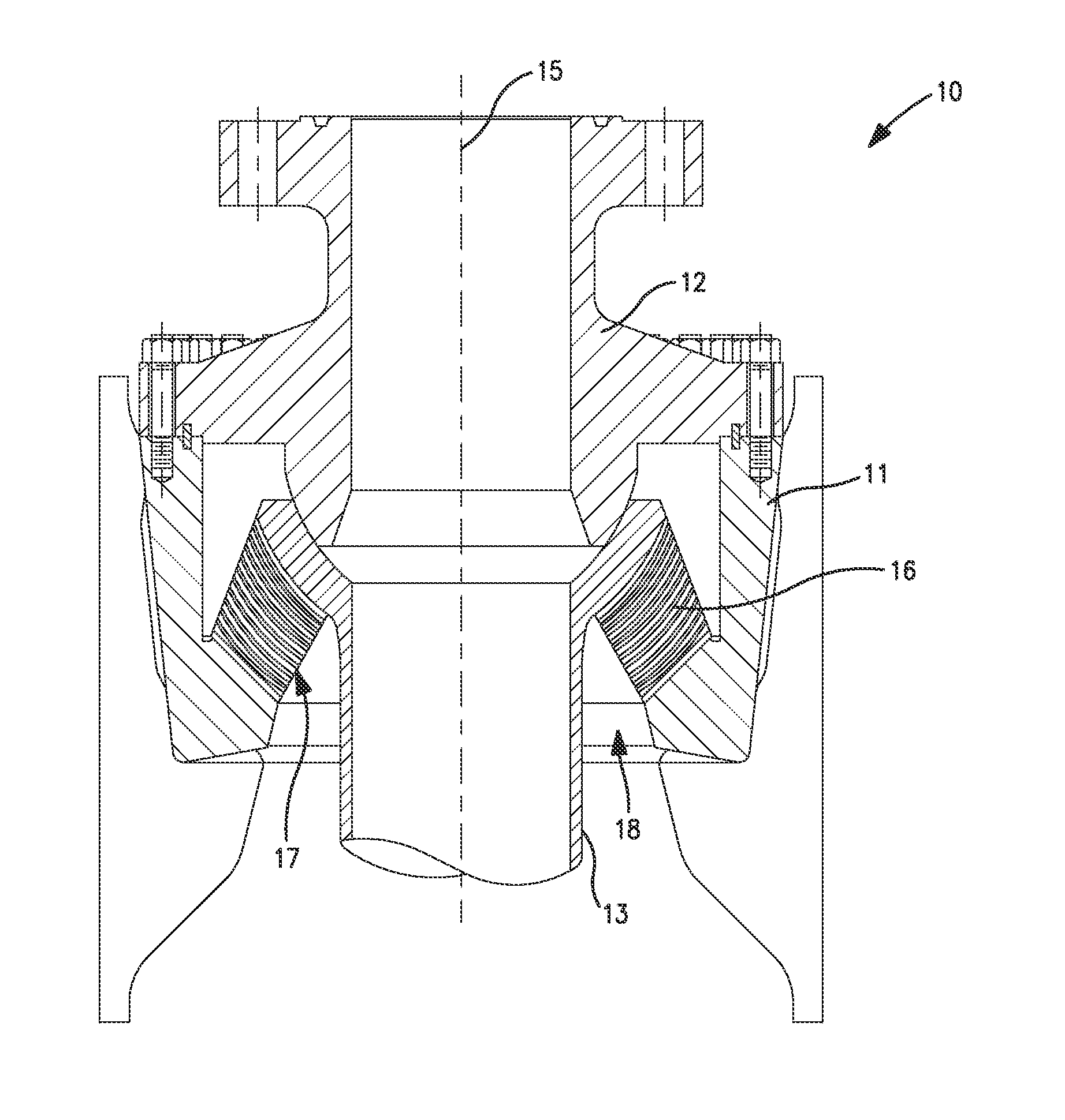
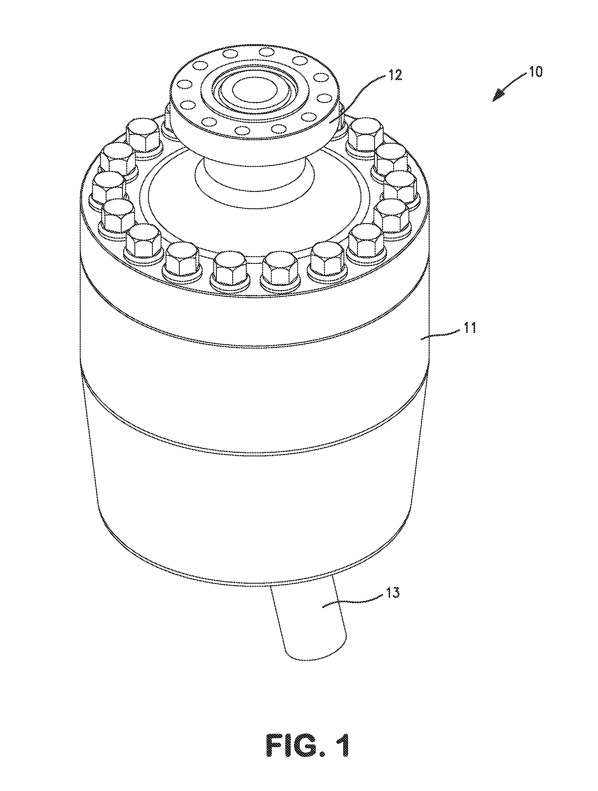
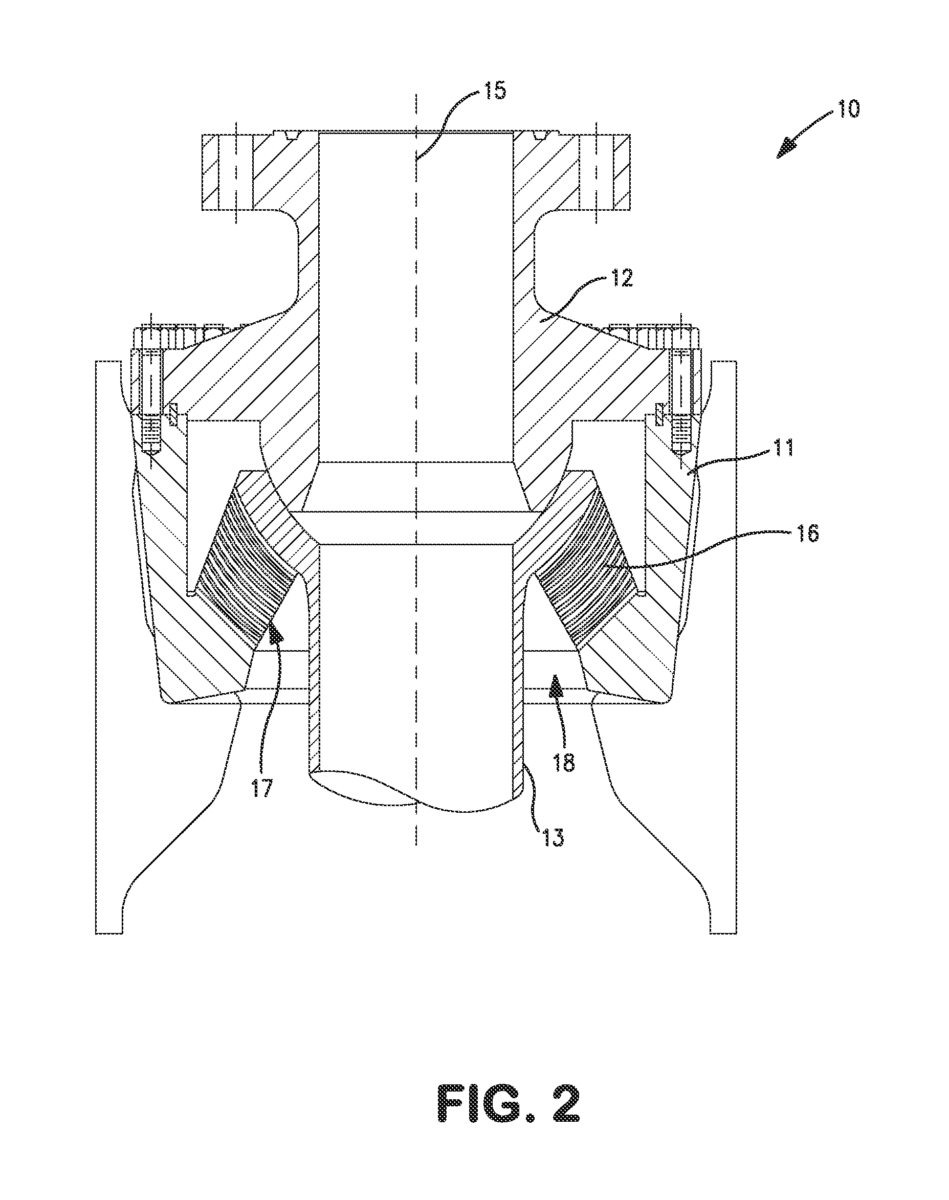
[0014]Apparatus and methods for inspecting and/or cleaning subsea flexible joints are disclosed herein. Embodiments disclosed herein provide remote access to a flex element of a subsea flexible joint and three degrees of movement for enhanced inspection and cleaning operations. Two degrees of movement are provided by a combination of a tool positioning assembly that allows for controlled rotation and radial motions along a guide assemb

Problems solved by technology

For example, ocean currents, wave motions and other external forces may create large bending stresses in the riser, which can lead to damage to and/or failure of the stress joint connecting the riser assembly to the subsea equipment.
Offshore drilling and production facilities in such dynamic ocean environments can experience extreme load conditions on the risers and mooring system components.
Extreme weather conditions alone, or in combination with equipment failures, may result in complex, simultaneous translational and rotational motions

Method used


Image

  • Apparatus and methods for inspecting and cleaning subsea flex joints
  • Apparatus and methods for inspecting and cleaning subsea flex joints
  • Apparatus and methods for inspecting and cleaning subsea flex joints

Examples


Embodiment Construction

[0034]The following discussion is directed to various embodiments of the invention. Although one or more of these embodiments may be preferred, the embodiments disclosed should not be interpreted, or otherwise used, as limiting the scope of the disclosure, including the claims. In addition, one skilled in the art will understand that the following description has broad application, and the discussion of any embodiment is meant only to be exemplary of that embodiment, and not intended to intimate that the scope of the disclosure, including the claims, is limited to that embodiment.

[0035]Certain terms are used throughout the following description and claims to refer to particular features or components. As one skilled in the art will appreciate, different persons may refer to the same feature or component by different names. This document does not intend to distinguish between components or features that differ in name but not function. The drawing figures are not necessarily to scale...


PUM


Abstract

A remotely operated device for inspecting and/or cleaning a subsea flexible pipe joint comprises a support assembly. In addition, the device comprises a tool positioning assembly coupled to the support assembly. The tool positioning assembly includes a rotating member disposed about a central axis. The tool positioning assembly is rotatable relative to the support assembly about the central axis. Further, the device comprises a cleaning assembly including a cleaning device adapted to clean the flexible pipe joint. The cleaning device is axially moveable relative to the rotating member. Still further, the device comprises a clamping assembly coupled to the support assembly. The clamping assembly has an open position disengaged with the section of the flexible pipe joint and a closed position engaging the section of the flexible pipe joint.

Description

CROSS-REFERENCE TO RELATED APPLICATIONS[0001]This application claims benefit of U.S. provisional application Ser. No. 61 / 141,537 filed Dec. 30, 2008, and entitled “Flex Joint Cleaning Tool,” which is hereby incorporated herein by reference in its entirety. This application also claims benefit of U.S. provisional application Ser. No. 61 / 152,889 filed Feb. 16, 2009, and entitled “Flex Joint Cleaning Tool,” which is hereby incorporated herein by reference in its entirety.STATEMENT REGARDING FEDERALLY SPONSORED RESEARCH OR DEVELOPMENT[0002]Not applicable.BACKGROUND[0003]1. Field of the Invention[0004]This disclosure relates generally to the field of subsea interventions. More specifically, the disclosure relates to devices and methods for cleaning subsea flex joints.[0005]2. Background of the Technology[0006]In many offshore operations, subsea pipestring or riser extending from subsea equipment to a rig or other structure at the surface of the water provides communication between the su...

Claims


Application Information

Patent Timeline
IPC IPC(8): E21B37/00
CPCE21B17/085E21B37/00B08B9/02
Inventor ANGEL, CHRISTOPHER ERICHARDEN, ERIC LEEPARTRIDGE, STUART DOUGLASGUINN, ANDREW J.
Owner BP CORP NORTH AMERICA INC
Why Eureka
Try Eureka